 EN
 IT Italiano
 ES Español
 FR Français
 DE Deutsch
Description
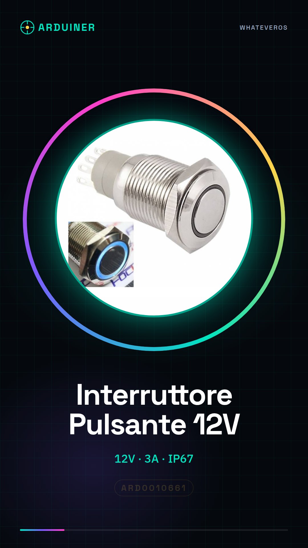
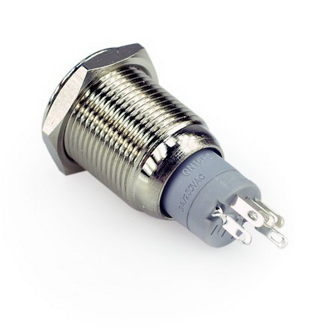
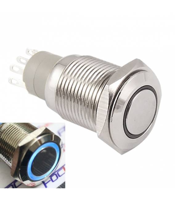
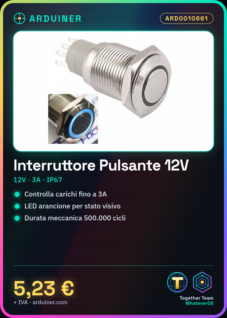
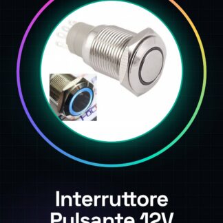
Self-Locking Push Button ON/OFF Switch with Blue LED 12V 16MM Metal Panel
Hole Size: 16MM
Control Method: Self-locking push button normally open, can control a load of 3A
Ring Light Voltage: 12V
Specification:
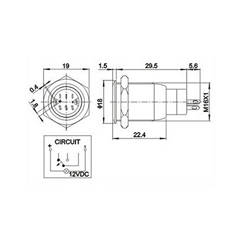
Tail Configuration: connection terminal (1,8 X 0,4)
Rated Power: 3 A / 250 V AC.
Contact Resistance: 50m
Insulation Resistance: 1000m
Dielectric Withstand Voltage: 2000VAC
Operating Temperature: -20 ~ + 55
Mechanical Life: 500,000 cycles
Electrical Life: 50,000 cycles
Panel Thickness: 1 – 15 mm
Torque: 5 to 14 Nm
Operating Force: approximately 3 – 5N
Operational Stroke: approximately 2,8 mm
Protection Level: IP67, IK10
Mounting hole cutout: 16 mm
Head diameter: 19 mm
Operation type: self-locking
Switch contact: 1NO1NC
Head shape: flat
LED type: illuminated ring
LED color: orange
Contact material: silver alloy
Button material: stainless steel
Base: PBT
Color: silver / chrome
Quantity: 1 x push button switch
Introduction:
This switch can be used for everything: window switches, motor start, headlights, fog lights, fire extinguisher kits, windshield kits – anything
Tutorial: How to use Self-Locking Push Button Switch with Blue LED 12V 16MM Metal Panel
This self-locking push button switch with blue LED is ideal for projects requiring manual and visual control. Useful for beginners and intermediates.
What you need
- Self-locking push button switch with blue LED 12V 16MM metal panel
- Connection wires
- 12V Power Supply
- Electronic Components to Control
Steps
- 1. Check the datasheet for the component specifications.
- 2. Mount the switch on the protection panel.
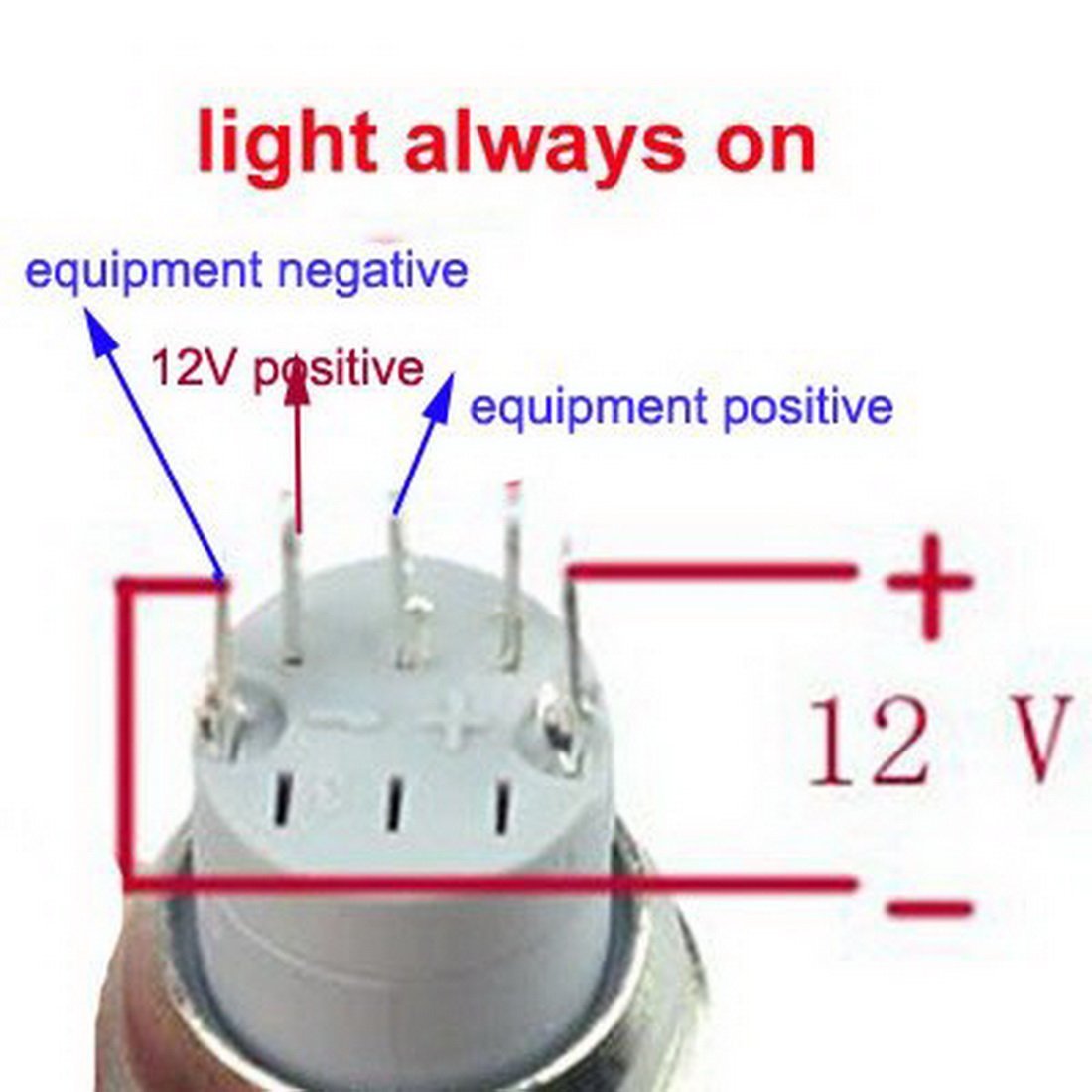
- 3. Connect the VCC pin to +12V.
- 4. Connect the GND pin to ground.
- 5. Connect the OUT pin to the component to control.
- 6. Connect the LED to the OUT pin (with polarity).
- 7. Verify the correct functioning of the button.
- 8. Check that the LED lights up when the button is pressed.
Mini project
Build a simple alarm circuit with the switch and an LED. Connect the switch to pin D2 of Arduino and the LED to pin D13. Write a simple code to check the state of the button and turn the LED on/off.
Common mistakes
- Connect VCC to ground.
- Ignore the polarity of the LED.
- Do not verify the correct functioning of the switch.
- Do not connect the OUT pin correctly.
Recommended accessories
- Arduino
- LED
- 220Ω Resistor
- Connection cable
Frequently asked questions
How can I verify the correct functioning of the switch?
Press the button and verify that the LED turns on/off correctly.
Can I use this switch with a 5V power source?
Check the datasheet to see if the component supports 5V. Otherwise, use a 12V power source.
Is the LED necessary for the use of the switch?
No, but it is useful for visual verification of the switch’s functioning.
Reviews
There are no reviews yet.