 EN
 IT Italiano
 ES Español
 FR Français
 DE Deutsch
Description
Technical Description
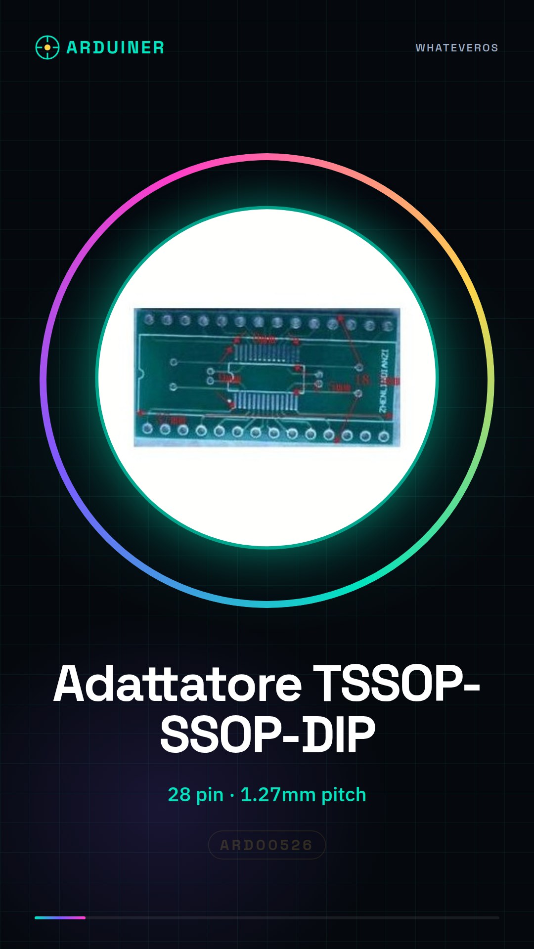
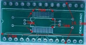
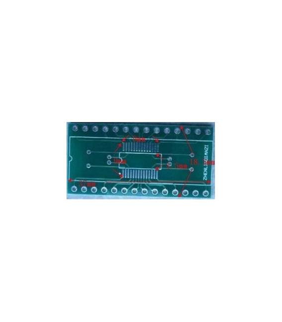
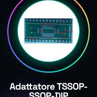
The TSSOP28 SSOP28 DIP28 Adapter Board is a component used to connect TSSOP28 or SSOP28 format chips to a DIP28 connector. This adapter allows chips like AD9851 and AD9850 to be used in a DIP connector, facilitating the design and testing of integrated circuits on test boards or printed circuits.
The component allows backward compatibility with 24 and 20 pin chips, making it versatile for use in various electronic design scenarios. The adapter board is designed to ensure a stable and secure connection between the chip and the DIP connector.
The adapter is particularly useful for projects that require signal generation or digital data manipulation, offering a simple and reliable way to connect surface-mount chips to a standard DIP connector.
Key Specifications
| Parameter | Value |
| Model | TSSOP28 SSOP28 DIP28 |
| Quantity | 1 |
| Dimensions | N/A (see manufacturer’s datasheet) |
| Interface | TSSOP28, SSOP28, DIP28 |
| Container | N/A (see manufacturer’s datasheet) |
Installation and Usage
- Check the datasheet for the pinout of the AD9851/AD9850 chip.
- Position the AD9851/AD9850 chip on the TSSOP28 SSOP28 board.
- Place the DIP28 adapter over the TSSOP28 SSOP28 board with the chip inserted.
- Secure by soldering the contacts of the adapter and DIP connector to the board.
- Check the datasheet for the power and data interfaces of the AD9851/AD9850 chip. Connect the power to the corresponding pins of the DIP28 adapter.
Compatibility and Requirements
- This adapter is compatible with AD9851 and AD9850 chips.
- Can be used with printed circuit boards that include a DIP connector.
- Requires a microcontroller or logic circuit to manage control and data signals.
- Compatibility with other TSSOP28 or SSOP28 chips depends on the chip’s datasheet specifications.
Limitations and Important Notes
- It is not designed for chips with a different number of pins than 28.
- Requires a thorough understanding of the chip specifications for proper installation.
- Using an adapter does not replace the need for a detailed chip datasheet.
- Ensure to use an appropriate support system for soldering and securing.
Troubleshooting
The chip does not respond after soldering.
Probable cause: Incorrect connection or missing connection to power pins.
Solution: Check connections and ensure power supply is correct.
The chip’s output signal is incorrect.
Probable cause: Microcontroller configuration error.
Solution: Check the datasheet specifications and microcontroller configuration.
The chip overheats during use.
Probable cause: Lack of heat dissipation.
Solution: Add heat sinks or redesign the circuit to improve thermal dissipation.
The chip does not respond when attempting to connect it.
Probable cause: Lack of power or incorrect connections.
Solution: Check power and connections to the power pins.
Use cases
Electronic Design Lab
Objective: Test the AD9851 chip in a test circuit.
What’s needed: TSSOP28 SSOP28 DIP28 adapter, AD9851 chip, printed circuit board with DIP connector.
Steps: 1) Check the chip pins. 2) Place the chip on the TSSOP28 SSOP28 board. 3) Place the DIP28 adapter over the chip. 4) Solder the adapter and DIP connector contacts. 5) Connect power to the corresponding pins.
Expected result: The AD9851 chip responds correctly to the test.
Signal Generation Project
Objective: Use the AD9851 chip to generate sinusoidal signals.
What’s needed: TSSOP28 SSOP28 DIP28 adapter, AD9851 chip, microcontroller.
Steps: 1) Check the chip pins. 2) Place the chip on the TSSOP28 SSOP28 board. 3) Place the DIP28 adapter over the chip. 4) Solder the adapter and DIP connector contacts. 5) Connect power to the corresponding pins. 6) Configure the microcontroller to generate sinusoidal signals.
Expected result: The AD9851 chip generates sinusoidal signals as expected.
Prototype Project
Objective: Test a TSSOP28 chip in a prototype circuit.
What’s needed: TSSOP28 SSOP28 DIP28 adapter, TSSOP28 chip, printed circuit board with DIP connector.
Steps: 1) Check the chip pins. 2) Place the chip on the TSSOP28 SSOP28 board. 3) Place the DIP28 adapter over the chip. 4) Solder the adapter and DIP connector contacts. 5) Connect power to the corresponding pins.
Expected result: The TSSOP28 chip responds correctly to the test.
Integrated Circuit Maintenance
Objective: Repair a TSSOP28 integrated circuit.
What’s needed: TSSOP28 SSOP28 DIP28 adapter, TSSOP28 chip, printed circuit board with DIP connector.
Steps: 1) Check the chip pins. 2) Place the chip on the TSSOP28 SSOP28 board. 3) Place the DIP28 adapter over the chip. 4) Solder the adapter and DIP connector contacts. 5) Connect power to the corresponding pins.
Expected result: The TSSOP28 integrated circuit functions correctly after repair.
Automation Project
Objective: Use the AD9851 chip to generate signals for an automation system.
What’s needed: TSSOP28 SSOP28 DIP28 adapter, AD9851 chip, microcontroller.
Steps: 1) Check the chip pins. 2) Place the chip on the TSSOP28 SSOP28 board. 3) Place the DIP28 adapter over the chip. 4) Solder the adapter and DIP connector contacts. 5) Connect power to the corresponding pins. 6) Configure the microcontroller to generate signals for the automation system.
Expected result: The AD9851 chip generates signals for the automation system as intended.
Electronic test project
Objective: Test the AD9851 chip in a test system.
What’s needed: TSSOP28 SSOP28 DIP28 adapter, AD9851 chip, printed circuit board with DIP connector.
Steps: 1) Check the chip pins. 2) Place the chip on the TSSOP28 SSOP28 board. 3) Place the DIP28 adapter over the chip. 4) Solder the adapter and DIP connector contacts. 5) Connect power to the corresponding pins.
Expected result: The AD9851 chip responds correctly to the test.
Advanced prototyping project
Objective: Test an SSOP28 chip in an advanced prototype circuit.
What’s needed: TSSOP28 SSOP28 DIP28 adapter, SSOP28 chip, printed circuit board with DIP connector.
Steps: 1) Check the chip pins. 2) Place the chip on the TSSOP28 SSOP28 board. 3) Place the DIP28 adapter over the chip. 4) Solder the adapter and DIP connector contacts. 5) Connect power to the corresponding pins.
Expected result: The SSOP28 chip responds correctly to the test.
Mass prototyping project
Objective: Test a TSSOP28 chip in a prototype mass circuit.
What’s needed: TSSOP28 SSOP28 DIP28 adapter, TSSOP28 chip, printed circuit board with DIP connector.
Steps: 1) Check the chip pins. 2) Place the chip on the TSSOP28 SSOP28 board. 3) Place the DIP28 adapter over the chip. 4) Solder the adapter contacts and DIP connector contacts. 5) Connect power to the corresponding pins.
Expected result: The TSSOP28 chip responds correctly to the test.
In the package
- 1 TSSOP28 SSOP28 DIP28 adapter for AD9851 AD9850 AD9851 chip
Complete the project
- 2 Pieces SOP28 SSOP28 TSSOP28 SMD to DIP 0.65 DIP 1.27mm Adapter Board: Used to connect TSSOP28 or SSOP28 format chips to a DIP28 connector.
- USB 2.0 to TTL/RS232 TTL UART Converter Module 6 Pin with CH340G chipUsed to convert USB serial communication to TTL/RS232 for communication with chips and microcontrollers.
- Raspberry Pi GPIO Adapter Board Type T 40 pin + cableUsed to connect the Raspberry Pi to a printed circuit board with a DIP connector.
Technical FAQs
Which chips are compatible with this adapter?
The component is compatible with AD9851 and AD9850 chips, and can be used with other TSSOP28 or SSOP28 chips based on the datasheet specifications.
How can I solve the overheating problem of the chip?
Add heat sinks or redesign the circuit to improve thermal dissipation.
What tools are needed for installation?
A soldering system, such as a soldering iron and pliers, is required.
How can I verify the correct installation of the chip?
Check the connections and ensure the power supply is correct, then test the chip according to the datasheet specifications.
Tutorial: How to use TSSOP28 SSOP28 DIP28 Adapter
This adapter allows the use of AD9851/AD9850 chips in a DIP connector. Ideal for signal generation projects.
What you need
- TSSOP28 SSOP28 DIP28 Adapter
- AD9851 or AD9850 chip
- Printed circuit board with DIP connector
Steps
- Check the datasheet for the pinout of the AD9851/AD9850 chip.
- Position the AD9851/AD9850 chip on the TSSOP28 SSOP28 board.
- Place the DIP28 adapter over the TSSOP28 SSOP28 board with the chip inserted.
- Secure by soldering the adapter and DIP connector contacts to the board.
- Check the datasheet for the power and data interfaces of the AD9851/AD9850 chip.
- Connect power to the corresponding pins of the DIP28 adapter.
- Connect the control and data signals to the microcontroller or logic circuit according to the datasheet specifications.
- Verify operation with an oscilloscope or logic analyzer.
Mini project
Generate a sine wave signal with AD9851 connected to an Arduino.
Common mistakes
- Incorrect soldering of contacts.
- Incorrect power pins.
- Control and data signals not correctly configured.
Recommended accessories
- Arduino Uno
- Portable Oscilloscope
- Soldering Kit
Frequently asked questions
Which chips can I use with this adapter?
AD9851 or AD9850, check the datasheet for specifications.
How do I verify the operation of the chip connected?
Use an oscilloscope to monitor the generated signals.
Reviews
There are no reviews yet.