 EN
 IT Italiano
 ES Español
 FR Français
 DE Deutsch
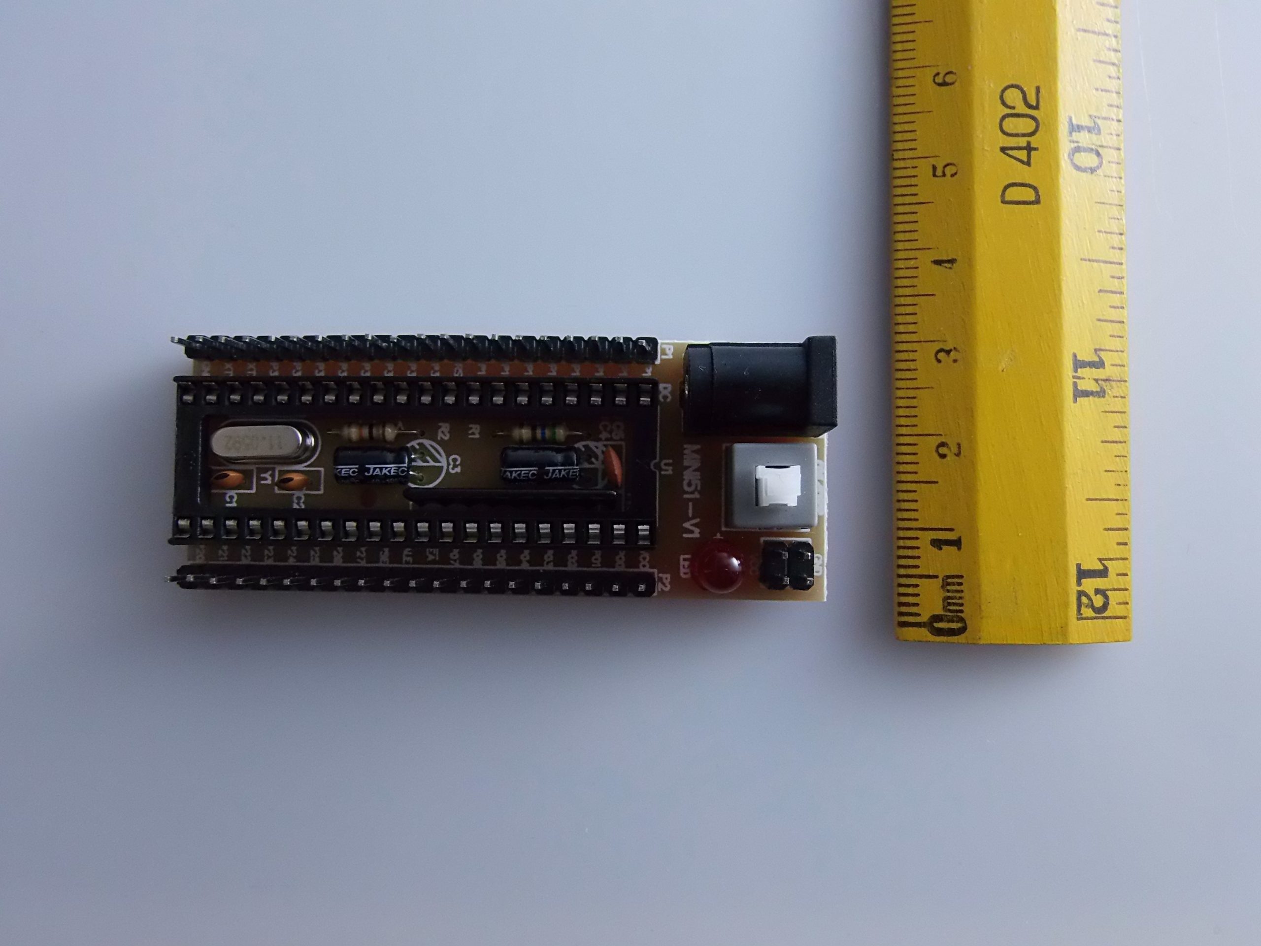
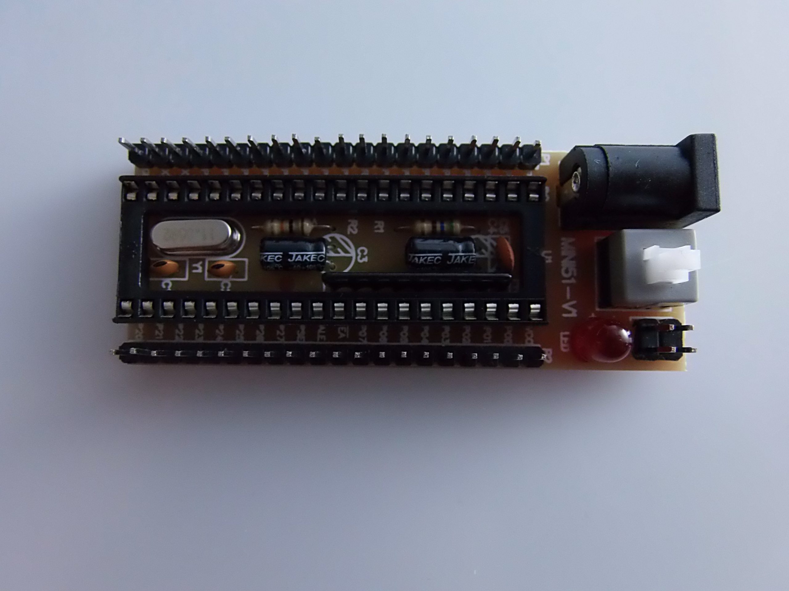
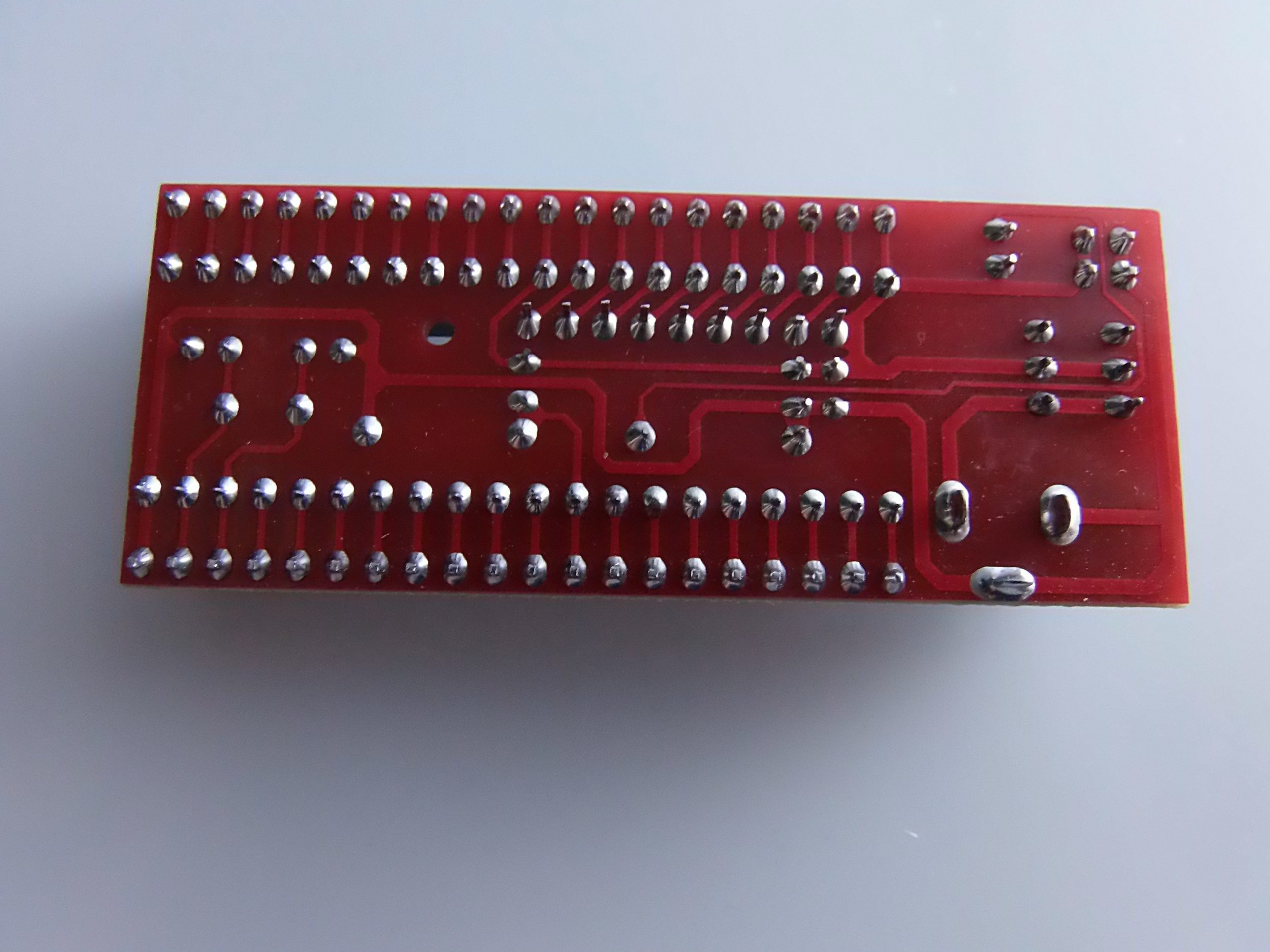
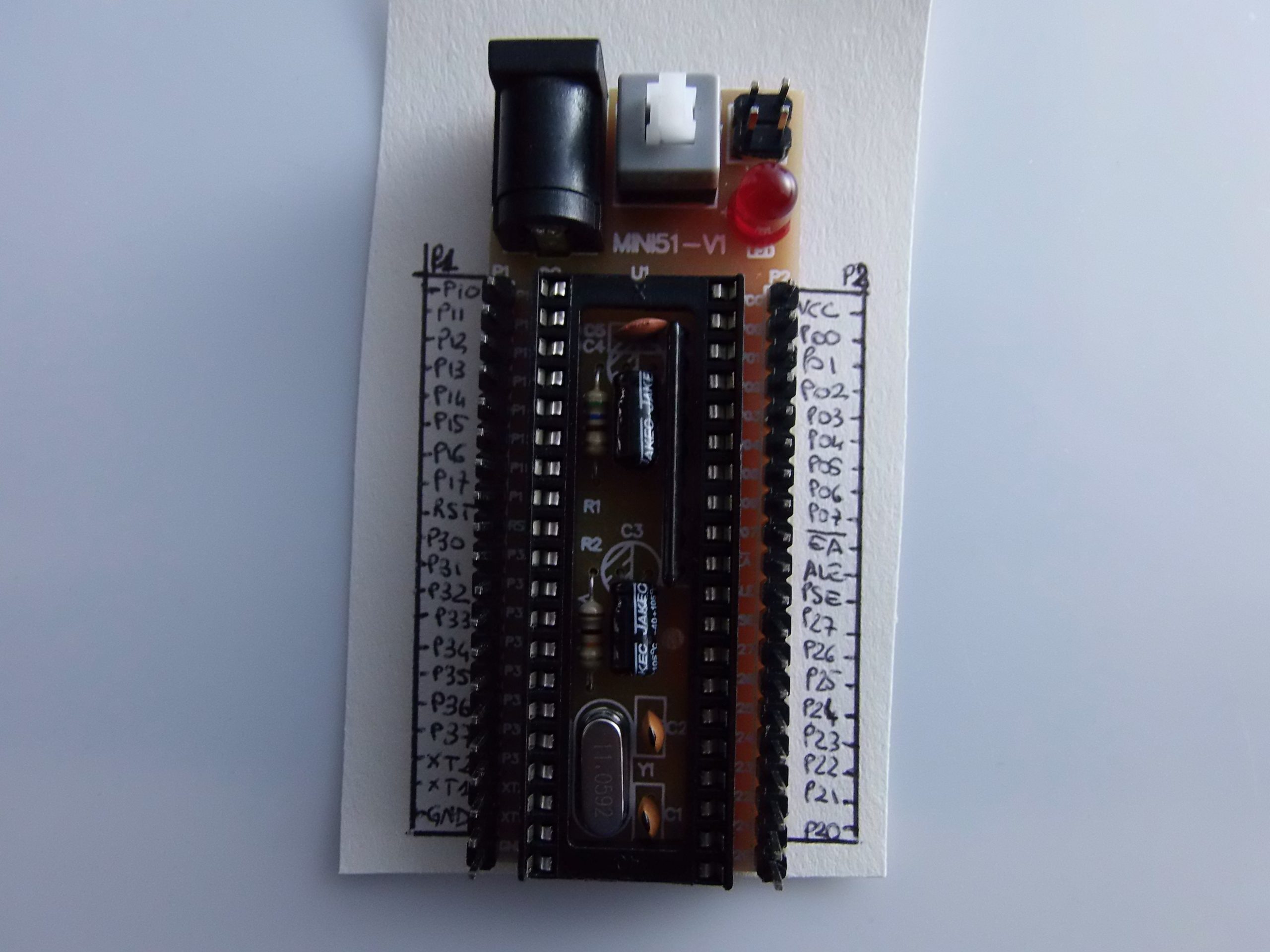
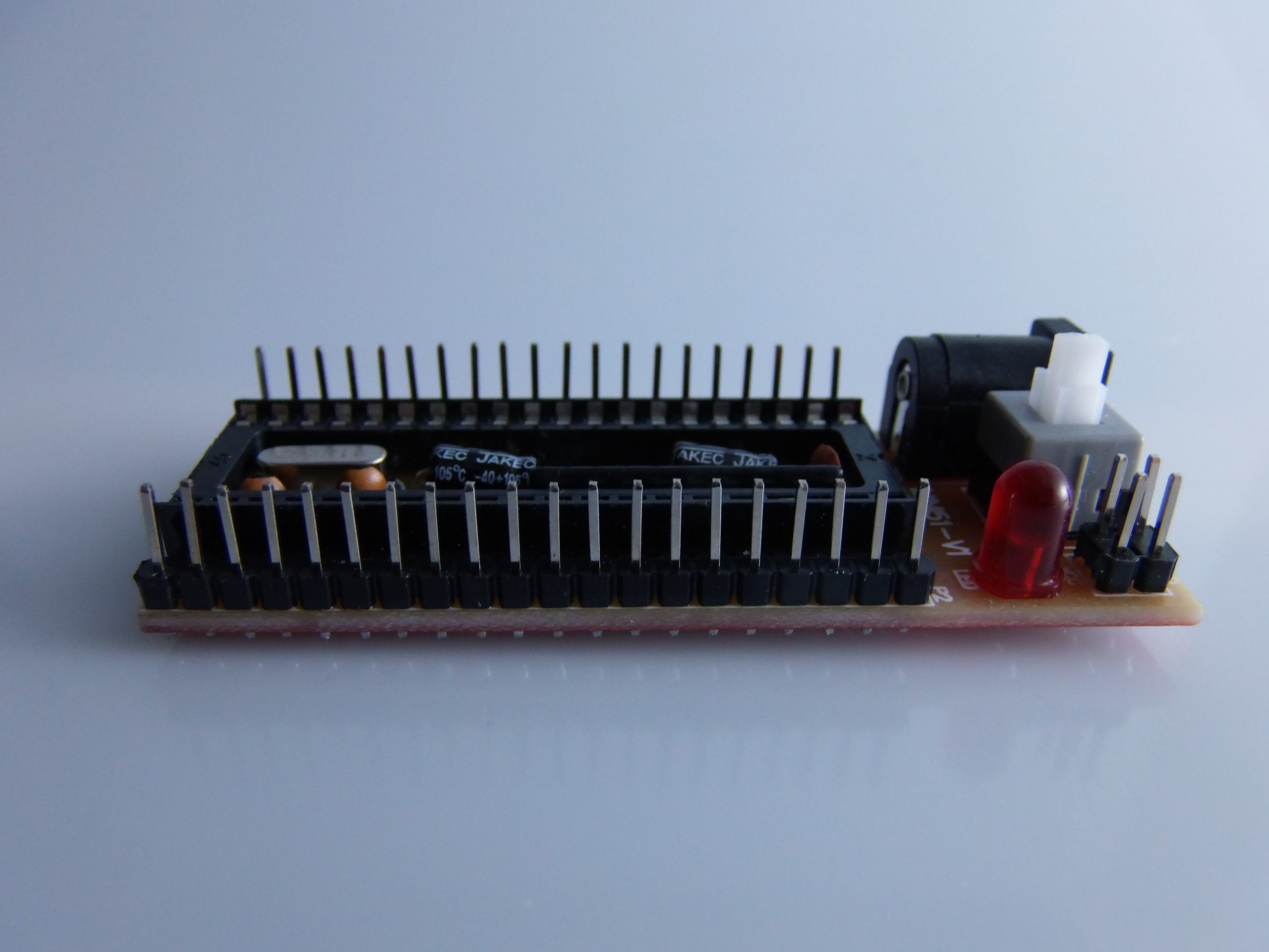
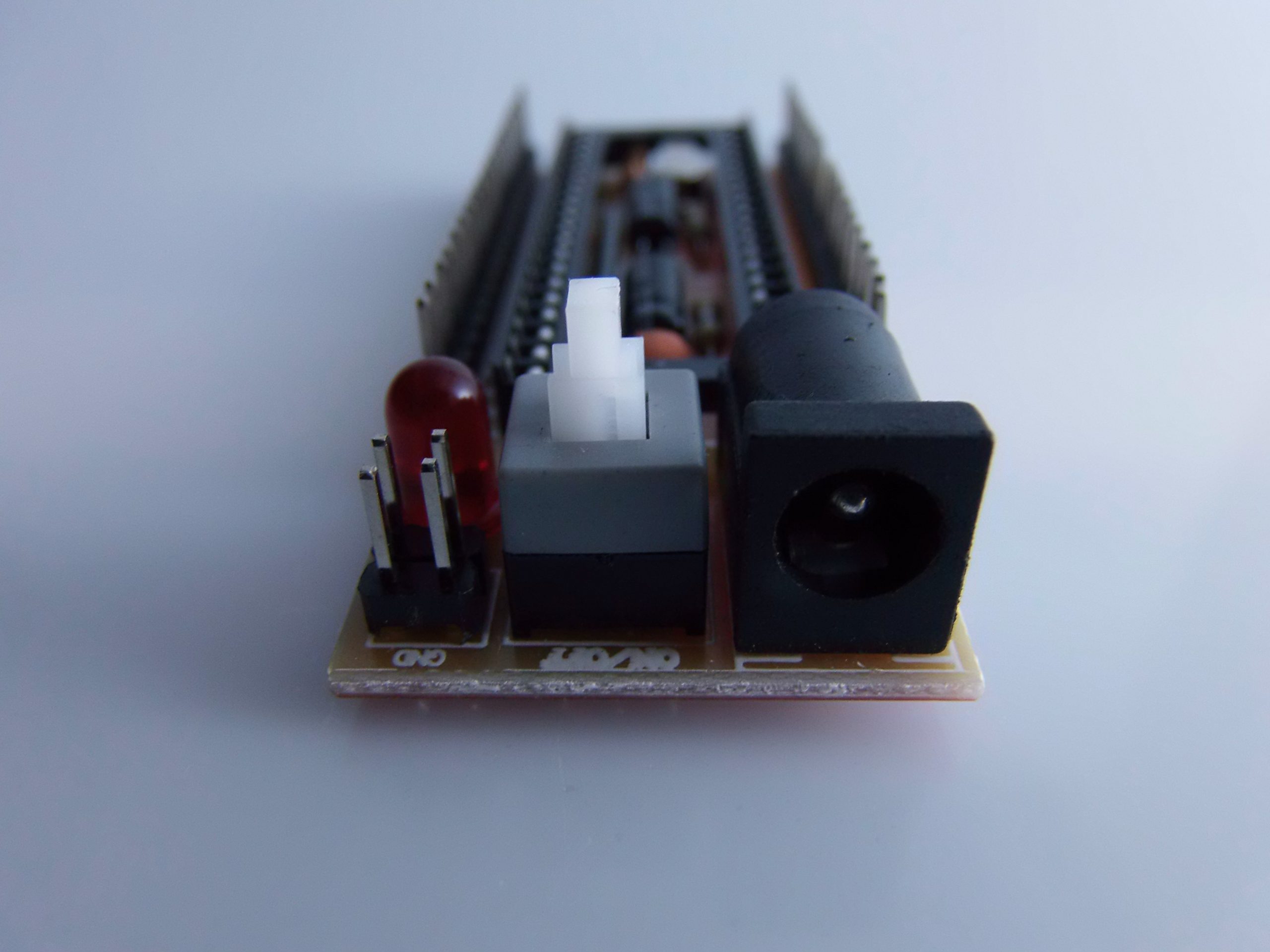
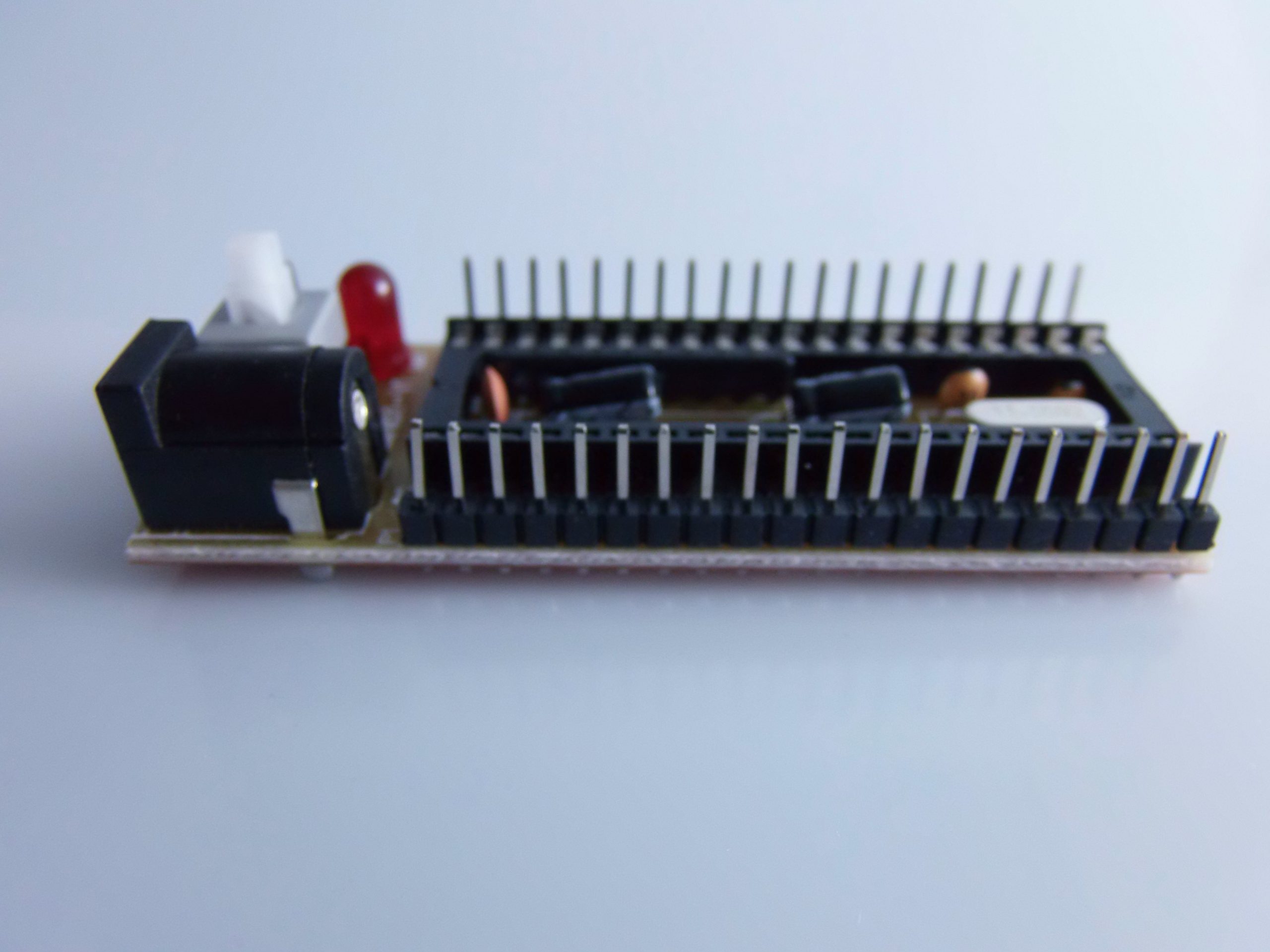
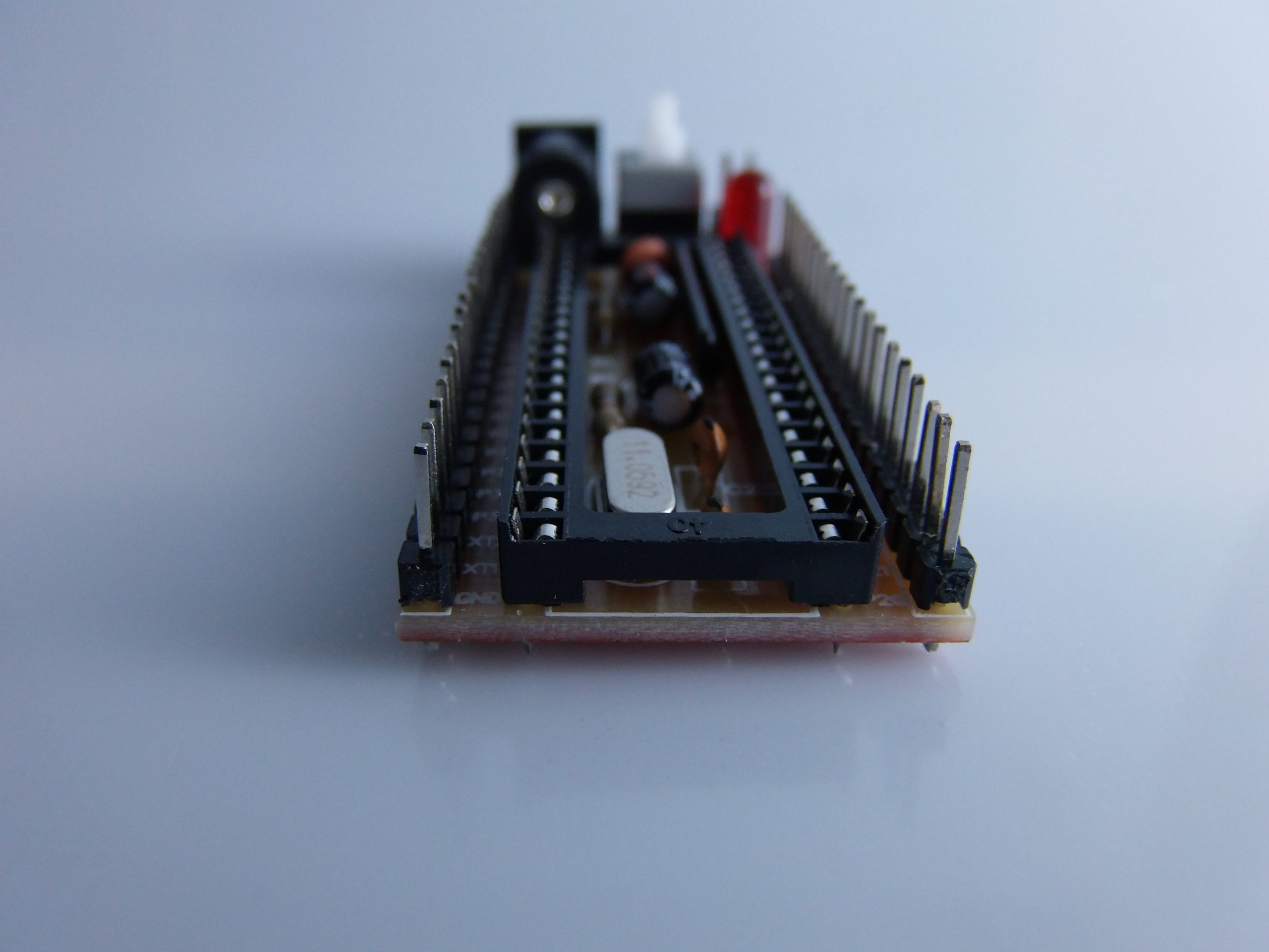
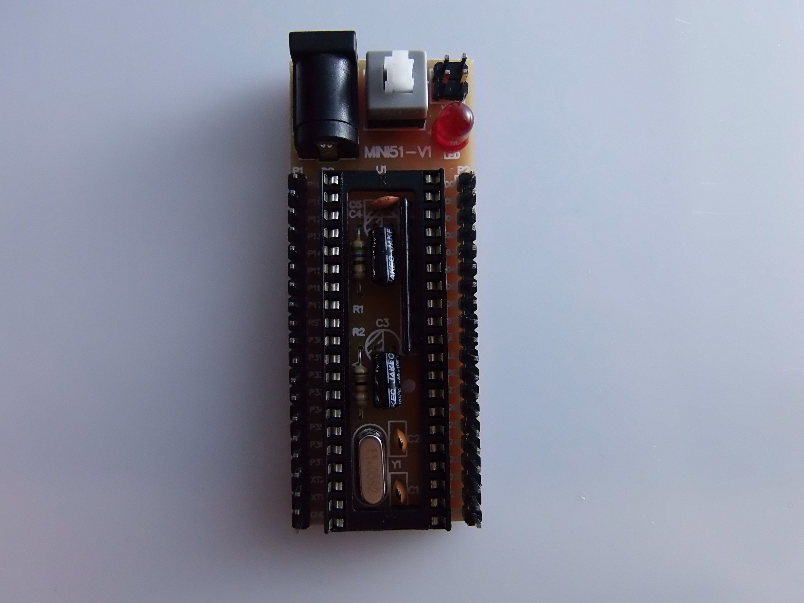
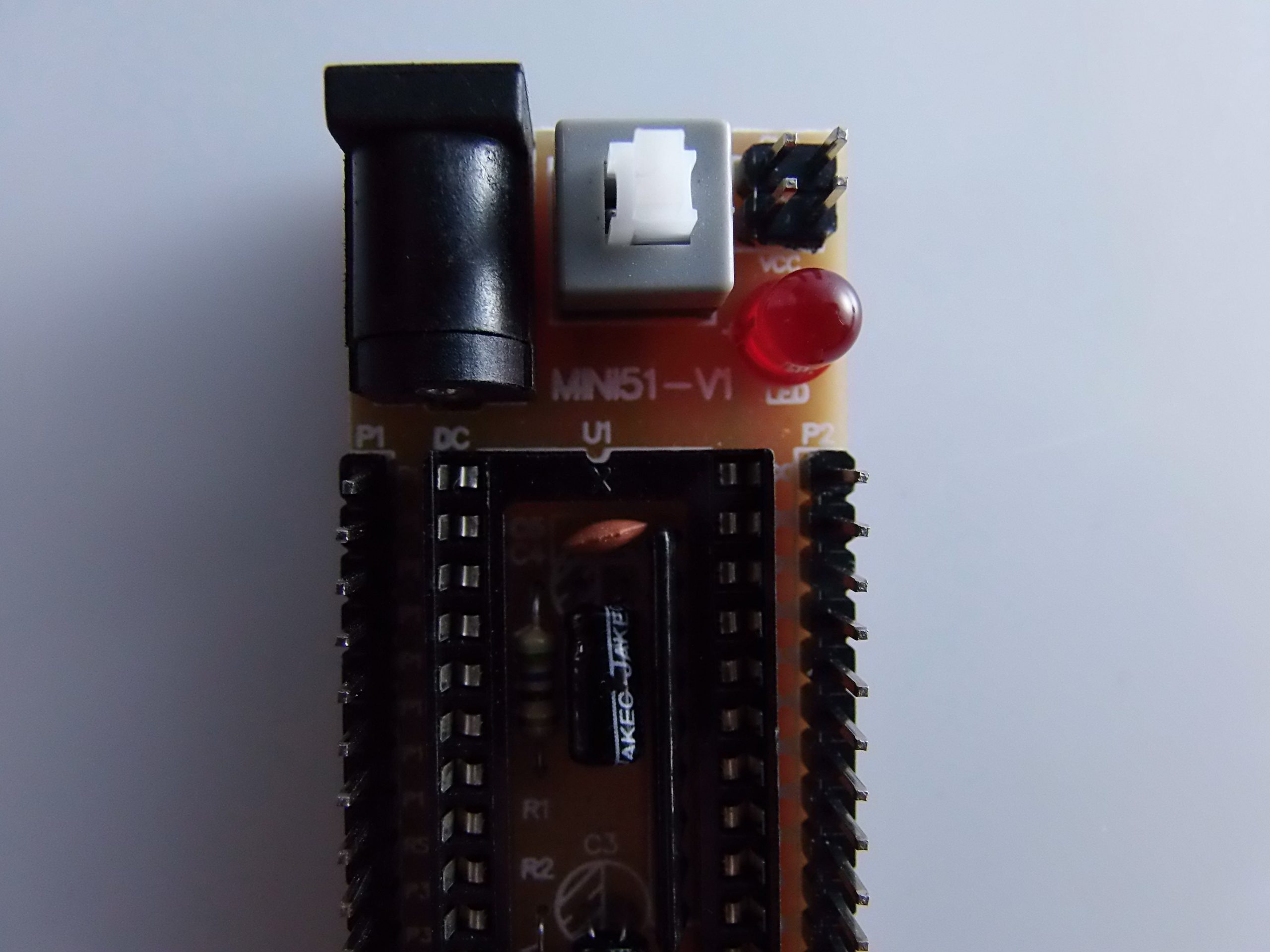
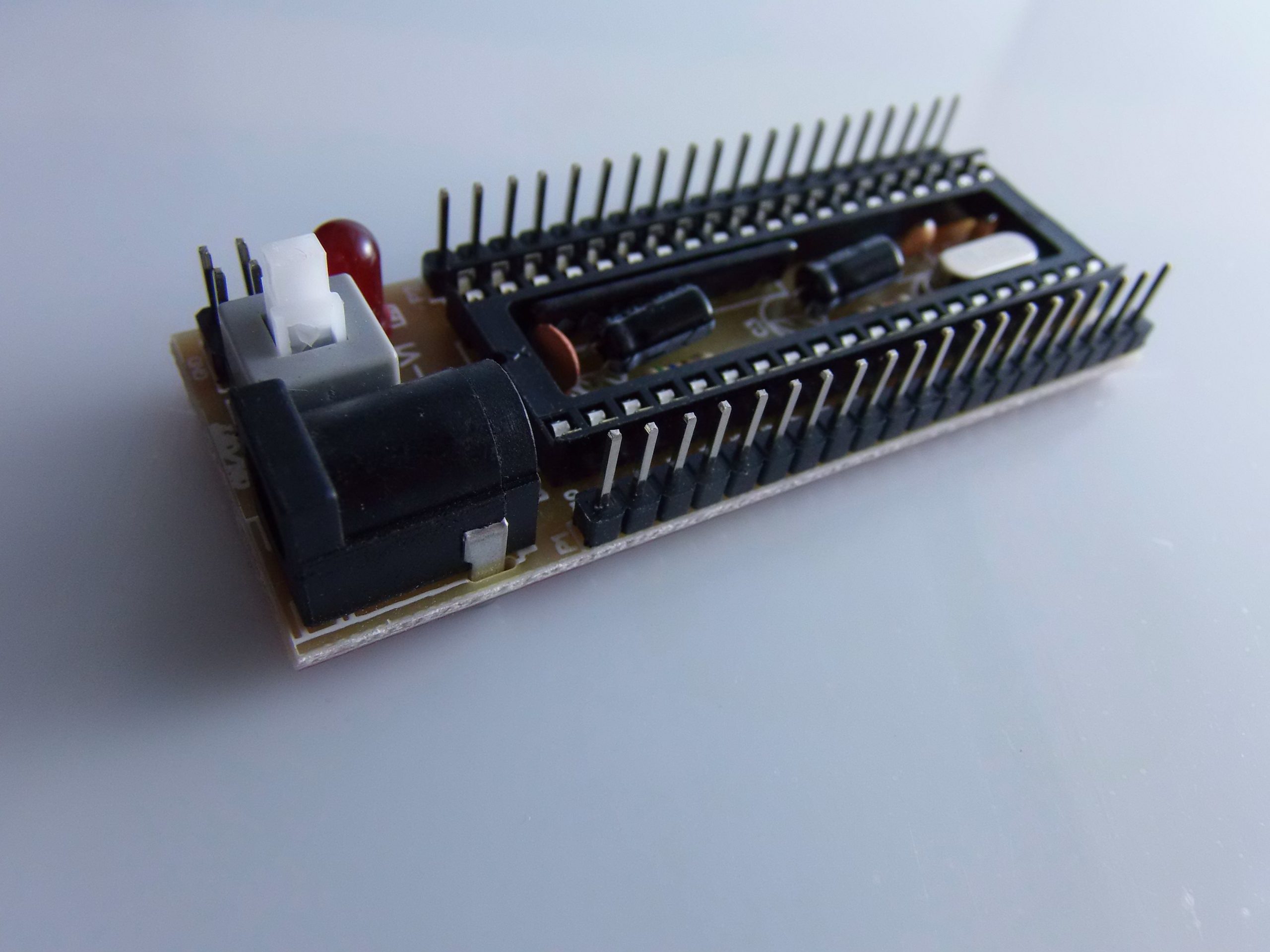
Description
🔧 YS-51 Development Board – Complete Description
📌 Overview
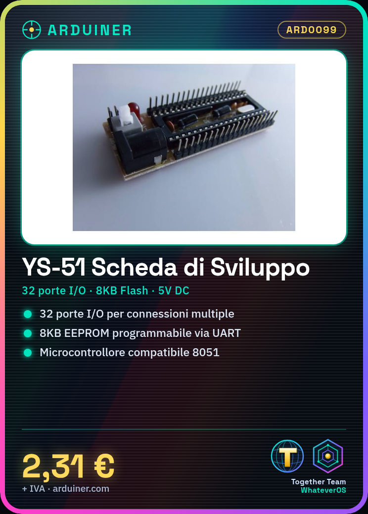
The YS-51 is a development board designed around the microcontroller STC89C52, belonging to the family STC (Single-chip microcomputer). It is an 8051-compatible microcontroller widely used in educational settings and for low-cost embedded applications.
🧠 Main Features
| Feature | Description |
|---|---|
| Microcontroller | STC89C52RC (Intel 8051 compatible) |
| Clock | 11.0592 MHz quartz oscillator (typical) |
| Internal RAM | 128 bytes |
| EEPROM/Flash | 8KB (programmable via UART) |
| GPIO | 32 I/O pins (4 ports of 8 bits) |
| Interfaces | UART, Timer, Interrupt, SPI/I2C (via bit-banging) |
| Operating Voltage | 5V DC |
| Programming | Through TTL serial port (UART) |
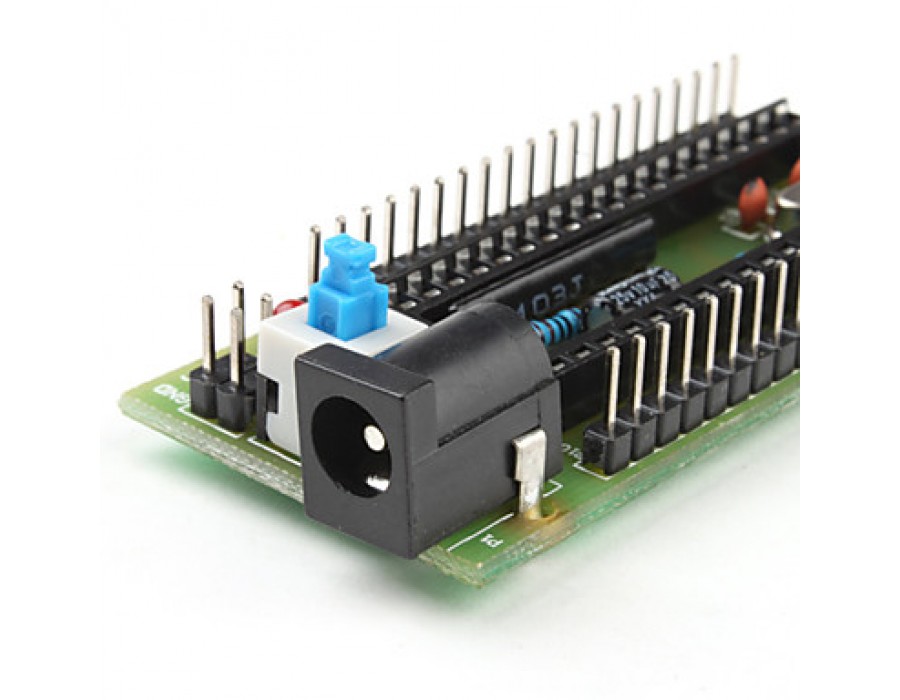
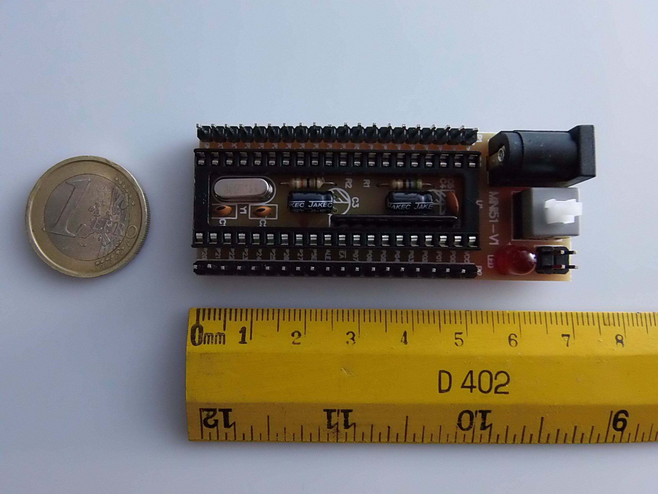
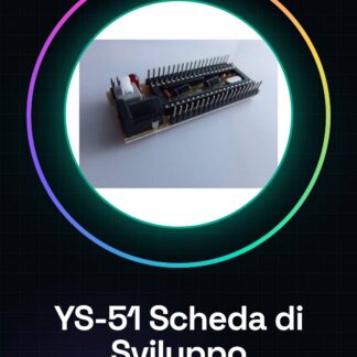
🔌 Components on the board
- Status LED
- Reset button
- External crystal
- Serial connector for programming
- Male connectors for each I/O port
- Power via USB or pin header
🔗 Compatibility with Arduino
The board YS-51 is not directly compatible with theArduino IDE as the microcontroller STC89C52 is not natively supported by Arduino (like ATmega328p, ATmega2560, etc.).
However, you can:
- Program the STC89C52 with its official software (STC-ISP).
- Use Arduino as a serial bridge to upload code to the STC.
- Or make them communicate via UART as separate devices.
🛠️ YS-51 Programming Guide
1️⃣ Required
- YS-51 Board
- USB-TTL Converter (e.g. CH340 or FTDI)
- Programming Software STC-ISP
- IDE to write the code: Keil uVision 5 (C language)
2️⃣ Connections for programming
Connect the pins as follows:
| YS-51 Pin | USB-TTL |
|---|---|
| TX | RX |
| RX | TX |
| GND | GND |
| VCC | 5V |
To start the programming:
- Press the button RESET on the YS-51.
- Start loading from the software STC-ISP.
- Release RESET.
3️⃣ Write a simple LED blink program
#include <reg52.h>

sbit LED = P1^0;

void delay_ms(unsigned int ms) {
    unsigned int i, j;
    for (i = 0; i < ms; i++)
        for (j = 0; j < 123; j++);
}

void main() {
    while (1) {
        LED = 0;
        delay_ms(500);
        LED = 1;
        delay_ms(500);
    }
}
4️⃣ Compilation and upload
- Compile the file
.cin Keil uVision → generate file.hex. - Open STC-ISP → select the correct COM port.
- Upload the file
.hexto the YS-51. - Press RESET to start.
🧪 Examples of Communication with Arduino
➕ Arduino as master UART
Wiring (serial communication):
| Arduino | YS-51 |
|---|---|
| TX | RX |
| RX | TX |
| GND | GND |
Arduino Code:
void setup() {
  Serial.begin(9600);
}

void loop() {
  Serial.println("Hello from Arduino");
  delay(1000);
}
STC Code (Keil C):
#include <reg52.h>
#include <stdio.h>

void UART_Init(void) {
    SCON = 0x50;  // UART mode 1
    TMOD = 0x20;  // Timer 1 mode 2
    TH1 = 0xFD;   // Baud rate 9600
    TL1 = 0xFD;
    TR1 = 1;      // Start Timer1
    TI = 1;
}

void main() {
    UART_Init();
    while (1) {
        if (RI) {
            RI = 0;
            P1 = SBUF;  // visualizza byte ricevuto su P1
        }
    }
}
🧭 Other Example Projects
- LCD 1602 Display with STC
- Control using compatible 8051 libraries.
- Seven Segment Counter
- Uses Timer + GPIO.
- Temperature Sensor (DS18B20 or LM35)
- Analog Reading (via external ADC) or digital (1-wire).
📚 Useful Resources
📌 Conclusion
The YS-51 is a versatile board for those who want to start with the 8051 architecture. Although it is not directly compatible with the Arduino ecosystem, it can be used to communicate with Arduino or programmed using dedicated tools. It offers an excellent way to learn the basics of traditional microcontrollers.
Let’s start with a specific complete project based on the YS-51 board (STC89C52): Relay control via button and serial communication with Arduino.
🔌 Project: Relay control with STC89C52 and communication with Arduino
🎯 Objectives
- Connect a button to activate/deactivate a relay module.
- Receive a command via serial from Arduino to activate/deactivate the relay.
- Send the relay status to Arduino.
🧱 Required Materials
| Component | Quantity |
|---|---|
| YS-51 with STC89C52 | 1 |
| Arduino Uno/Nano | 1 |
| 5V relay module | 1 |
| Button + 10kΩ resistor | 1 |
| Dupont cables | various |
| 5V power supply | 1 |
🔌 Connection Diagram
YS-51 → Relay
| STC89C52 | Relay |
|---|---|
| P1.0 | IN (signal) |
| GND | GND |
| VCC | VCC |
YS-51 → Button
| Button | STC89C52 |
|---|---|
| One end | P1.1 |
| Other end | GND |
Use a internal pull-up or an external 10kΩ resistor between P1.1 and VCC.
YS-51 ↔ Arduino (UART)
| STC89C52 | Arduino |
|---|---|
| TX (P3.1) | RX |
| RX (P3.0) | TX |
| GND | GND |
💾 STC89C52 Code (Keil C)
#include <reg52.h>
#include <stdio.h>

sbit RELAY = P1^0;
sbit BUTTON = P1^1;

void UART_Init(void) {
    TMOD = 0x20;       // Timer1 Mode2
    TH1 = 0xFD;        // 9600 baud
    TL1 = 0xFD;
    TR1 = 1;           // Start timer
    SCON = 0x50;       // UART mode 1, 8-bit, enable RX
    TI = 1;            // Set transmit ready
}

void UART_SendString(char *s) {
    while (*s) {
        SBUF = *s++;
        while (!TI);
        TI = 0;
    }
}

void delay_ms(unsigned int ms) {
    unsigned int i, j;
    for (i = 0; i < ms; i++)
        for (j = 0; j < 123; j++);
}

void main() {
    UART_Init();
    RELAY = 0;  // relè OFF

    while (1) {
        if (BUTTON == 0) {  // premuto (collegato a GND)
            RELAY = !RELAY;  // cambia stato
            UART_SendString(RELAY ? "Relay ONn" : "Relay OFFn");
            delay_ms(500);  // debounce
        }

        if (RI) {
            char cmd = SBUF;
            RI = 0;

            if (cmd == '1') {
                RELAY = 1;
                UART_SendString("Relay ONn");
            } else if (cmd == '0') {
                RELAY = 0;
                UART_SendString("Relay OFFn");
            }
        }
    }
}
💻 Arduino Code (Serial Monitor + Command Sending)
void setup() {
  Serial.begin(9600);
}

void loop() {
  if (Serial.available()) {
    String stato = Serial.readStringUntil('n');
    Serial.println("STC ha risposto: " + stato);
  }

  if (Serial.availableForWrite()) {
    char comando = Serial.read();
    // Comandi manuali da Serial Monitor
    if (comando == '1') Serial.write('1');
    else if (comando == '0') Serial.write('0');
  }

  // Simula un comando automatico ogni 5 sec
  static unsigned long t = millis();
  if (millis() - t > 5000) {
    Serial.write('1');
    delay(2000);
    Serial.write('0');
    t = millis();
  }
}
⚙️ Keil uVision and STC-ISP Installation (Step by Step)
🔽 1. Download the tools
- Keil uVision5:
https://www.keil.com/download/product/ - STC-ISP Programmer (v6.85 or similar):
http://www.stcmcu.com/datasheet/stc-isp-15xx-v6.85.zip
🧰 2. Keil Installation
- Start the setup.
- During the installation, select “8051 microcontroller support”.
- Create a new project:
- Target:
STC89C52RCoGeneric 8051 - Add file
.c
- Target:
- Compile (
F7) → get file.hex.
💾 3. Use of STC-ISP
- Connect the YS-51 via USB-TTL.
- Start
STC-ISP. - Select:
- Correct COM port
- Chip type:
STC89C52RC - Load file
.hex
- Press RESET on the board.
- Click “Download/Program”.
- Wait for confirmation (time: about 3–4 seconds).
✅ Final Test
- Pressing the button on YS-51, the relay switches on/off.
- From the Arduino serial monitor, send
'1'o'0'. - Check the output feedback from STC → Arduino → PC.
Tutorial: How to Use YS 51 Development Board STC
The YS 51 board on STC is ideal for makers who want to explore the world of low-cost microcontrollers. It is a single chip integrated into a complete development board, suitable for both beginners and intermediate developers.
What you need
- YS 51 Development Board STC
- USB to micro-USB connection
- Arduino IDE installed
Steps
- Connect the USB cable to the YS 51 board and the computer hardware.
- Open Arduino IDE and select ‘STC89C52RC’ as the device in the ‘Tools > Boards’ menu.
- Check the firmware version installed on the board. If necessary, download and install the latest version from the official website.
- Load an example sketch from the Arduino library (e.g., Blink) to test the connection.
- Select ‘File > New’ in Arduino IDE and copy-paste the sketch provided in the tutorial.
- Compile and upload the sketch to the YS 51 microcontroller.
- Verify the correct execution of the code by monitoring the outputs through the Arduino Serial Monitor.
- Explore further functionalities of the board by following the documents provided by the manufacturer.
Example code
// Includi la libreria necessaria
#include <STC89.h>
// Definisci le pin
#define LED_BUILTIN 13
void setup() {
  pinMode(LED_BUILTIN, OUTPUT);
}
void loop() {
  digitalWrite(LED_BUILTIN, HIGH);   // Accendi il LED
  delay(1000);                       // Attende un secondo
  digitalWrite(LED_BUILTIN, LOW);    // Spegni il LED
  delay(1000);                       // Attende un secondo
}
Mini project
Create a small night light with the YS 51 STC Development Board. Connect a light sensor and program the board to automatically turn on a light bulb when it gets dark.
Common mistakes
- Ensure that the Arduino IDE is correctly configured with the settings for the microcontroller.
- Check the USB connections between the computer and the board.
- Check for any compilation errors in the loaded code.
- Check hardware compatibility between the YS 51 board and the development hardware used.
Recommended accessories
- USB to micro-USB cable
- JTAG cable for debugging
- Breadboard
- Various sensors
Frequently asked questions
Where can I find the datasheet for the YS 51 board?
The datasheet is available on the manufacturer’s website or in the ‘documentation’ folder of the Arduino IDE installation package.
Can I use the YS 51 with programming languages other than C/C++?
Most of the board’s features are accessible through the Arduino IDE, but you may need to install additional libraries to use other languages.
What is the difference between YS 51 and Arduino Uno?
The YS 51 is a low-cost microcontroller with limited functionality compared to the Arduino Uno, but it offers an economical solution for simple projects.
Reviews
There are no reviews yet.