 EN
 IT Italiano
 ES Español
 FR Français
 DE Deutsch
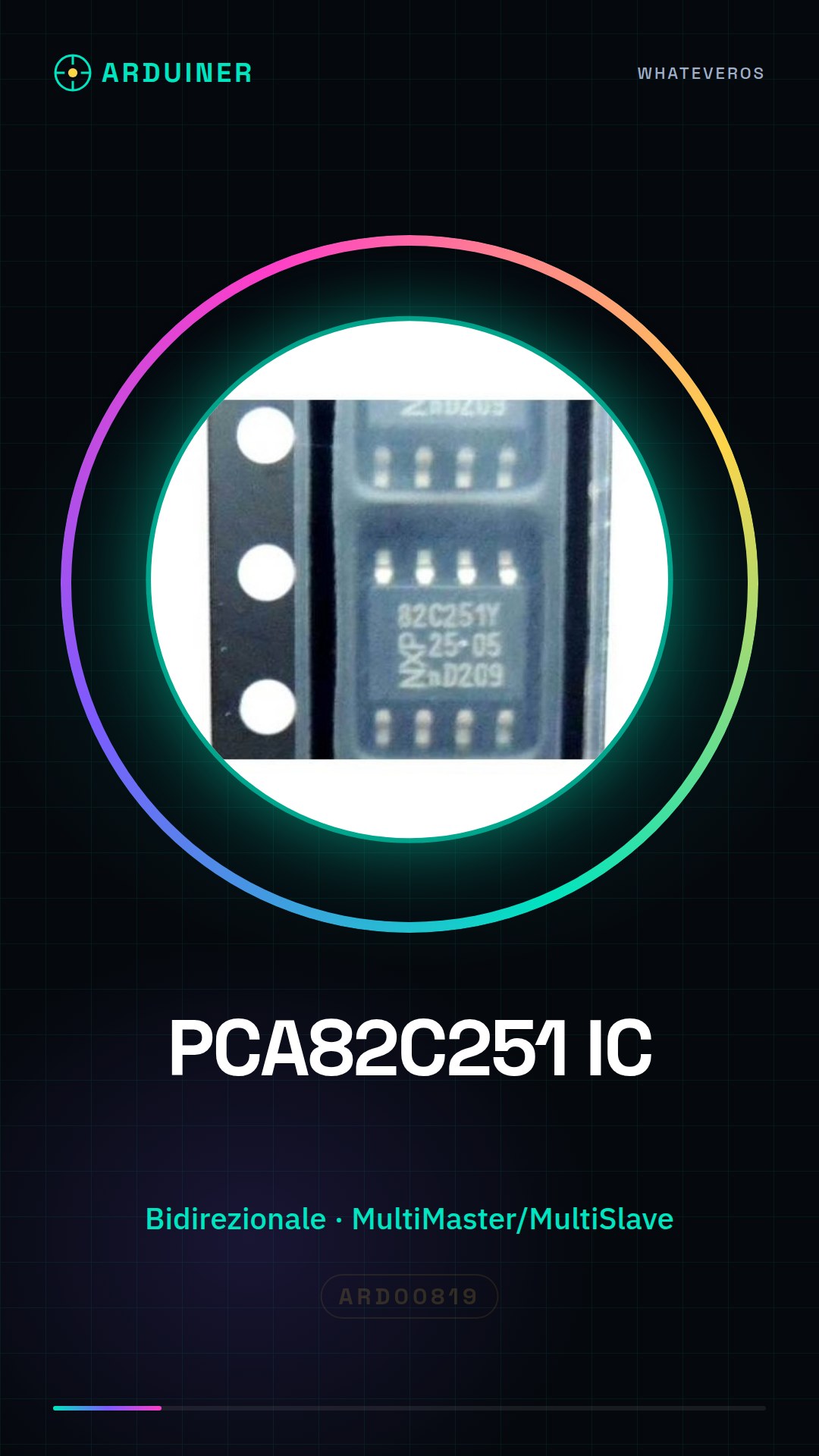
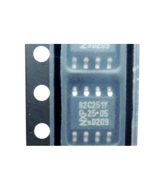
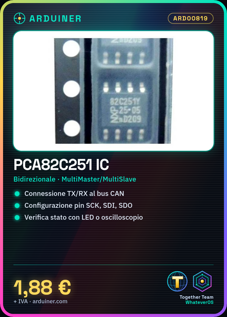

Description
Component specifications: …
Tutorial: How to use PCA82C251
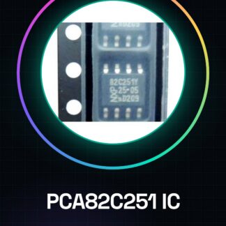
The PCA82C251 is an integrated circuit used for network communication between electronic devices. It is ideal for projects requiring multi-point serial connections (MultiMaster/MultiSlave) on bidirectional data lines.
What you need
- CAN bus projects
- Robust serial networks
- Industrial communication systems
Steps
- Check the PCA82C251 compatibility with your electronic project.
- Set up a test circuit on a prototype board or 3D printed circuit.
- Connect Vcc and GND to the system voltage reference.
- Connect TX and RX to your CAN network bus.
- Verify the correct configuration of control pins (SCK, SDI, SDO) according to the datasheet specifications.
- Cycle the circuit to test the activity of status LEDs if present.
- Use an oscilloscope or logic analyzer to monitor CAN signals.
- Configure the software for CAN communication.
Mini project
Create a simple CAN network with two microcontrollers exchanging test messages.
Common mistakes
- Connect the TX and RX pins in reverse.
- Omit the required pull-up resistance for the CAN bus.
- Incorrectly configure the CAN communication parameters in the software.
- Ignore the importance of temporal synchronization between CAN nodes.
Recommended accessories
- Pull-up resistors
- Capacitive decoupling for stable power supply
- Oscilloscope or logic analyzer
- Microcontrollers with CAN support
Frequently asked questions
Is the PCA82C251 compatible with Arduino?
Yes, but it requires a specific software implementation for CAN communication.
What are the recommended transmission speeds?
Check the datasheet for the limits of your configuration.
Reviews
There are no reviews yet.