 EN
 IT Italiano
 ES Español
 FR Français
 DE Deutsch
Description
Technical Description
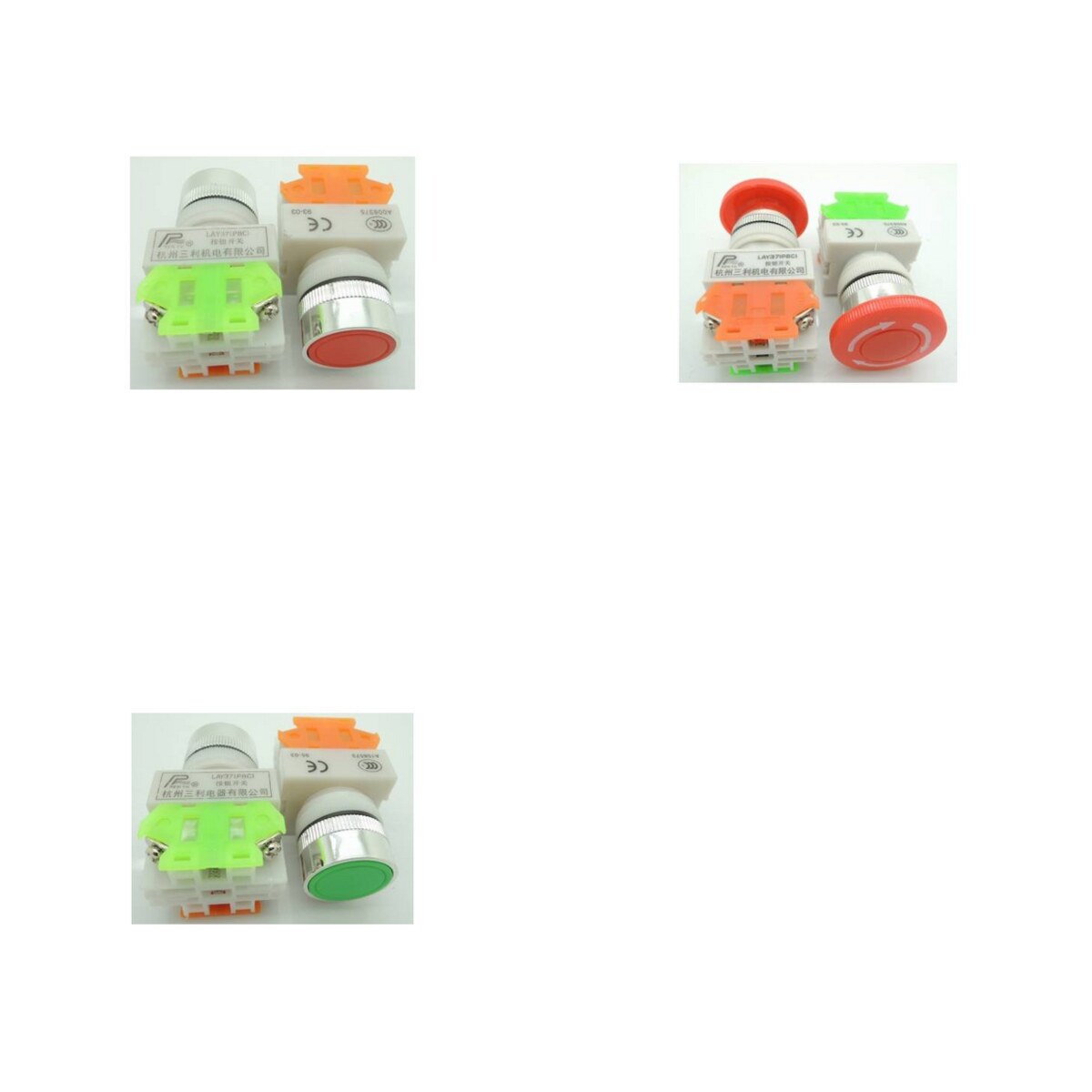
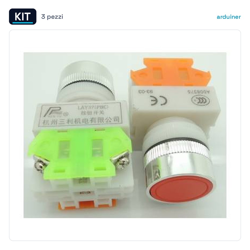
The Kit Red LAY37-11 bn (Y090-11 bn)flat button Push Button, LAY37-11ZS (Y090) button au and Green LAY37-11 bn (Y090-11 bn)flat button Push Button is a set of snap-action buttons, used in electronic control applications where a switch with rapid state changes is required. These buttons offer two contacts, one normally open (NO) and one normally closed (NC), which alternate when the button is pressed. The kit is designed to offer a choice of colors and types of buttons for various applications.
The buttons in the kit are suitable for the realization of electronic prototypes and projects, providing a simple and reliable user interface. Their application includes control systems, emergency switches, and any situation where a switch with rapid state changes is needed.
Each button in the kit features a flat and robust design with a secure and repeatable contact. The presence of buttons in different colors allows for easy identification of different functions in a circuit or system.
Key Specifications
| Parameter | Value |
| Red Model | LAY37-11 bn (Y090-11 bn) |
| Self-Locking Model | LAY37-11ZS (Y090) |
| Green Model | LAY37-11 bn (Y090-11 bn) |
| Contacts | 1NO + 1NC |
| Dimensions | N/D (see manufacturer’s datasheet) |
| Container | N/D (see manufacturer’s datasheet) |
| Quantity | 3 |
Installation and Usage
- Check the compatibility of the buttons with the electronic circuit.
- Connect the NO and NC contacts of the buttons to the control circuit.
- Power the circuit with the appropriate voltage.
- Press the buttons to verify the operation of the contacts.
- Perform an initial test of the circuit to ensure that the buttons work correctly.
Compatibility and Requirements
- The kit is compatible with various boards and electronic systems, such as Arduino, Raspberry Pi, and other microcontrollers.
- An electronic control circuit is required to connect the buttons.
- Compatibility with the circuit depends on the voltage and current of the system.
Limitations and Important Notes
- The buttons are not designed for applications with high voltages or high currents.
- Be careful to correctly identify the NO and NC contacts during connection.
- Ensure that the control circuit is designed to handle the type of contacts offered by the buttons.
- The buttons are not designed to withstand extreme temperature or humidity conditions.
Troubleshooting
The contacts do not change state when the button is pressed.
Probable cause: Incorrect connection of NO and NC contacts.
Solution: Check and correct the connection of the contacts.
The latching button does not unlatch.
Probable cause: Incorrect connection of the latching function.
Solution: Check and correct the connection of the latching function.
The contacts do not change state when the button is pressed.
Probable cause: Insufficient supply voltage.
Solution: Check and increase the supply voltage.
The button does not respond.
Probable cause: Mechanical damage to the button.
Solution: Replace the damaged button.
Use cases
Parking sensor for the garage
Objective: Alert the user when a vehicle enters the garage.
What is needed: A button to start the alarm system.
Steps: 1) Connect the button to the control circuit. 2) Power the circuit. 3) Check the operation of the alarm system.
Expected result: The alarm system is activated when the button is pressed.
User interface for an industrial control system
Objective: Allow staff to interact with the control system.
What is needed: Buttons to activate and deactivate system functions.
Steps: 1) Connect the buttons to the control circuit. 2) Power the circuit. 3) Check the operation of the buttons. 4) Test the system’s response to button actions.
Expected result: The system responds correctly to button actions.
User interface for a home security system
Objective: Allow the user to activate and deactivate the security system.
What is needed: Buttons to activate and deactivate the security system.
Steps: 1) Connect the buttons to the control circuit. 2) Power the circuit. 3) Verify the functionality of the buttons. 4) Test the system’s response to button actions.
Expected result: The security system responds correctly to button actions.
User interface for an access control system
Objective: Allow the user to activate and deactivate the access control system.
What is needed: Buttons to activate and deactivate the access control system.
Steps: 1) Connect the buttons to the control circuit. 2) Power up the circuit. 3) Verify the functionality of the buttons. 4) Test the system’s response to button actions.
Expected result: The access control system correctly responds to button actions.
User interface for a temperature control system
Objective: To allow the user to activate and deactivate the temperature control system.
What is needed: Buttons to activate and deactivate the temperature control system.
Steps: 1) Connect the buttons to the control circuit. 2) Power up the circuit. 3) Verify the functionality of the buttons. 4) Test the system’s response to button actions.
Expected result: The temperature control system correctly responds to button actions.
User interface for a lighting control system
Objective: To allow the user to activate and deactivate the lighting control system.
What’s needed: Buttons to activate and deactivate the lighting control system.
Steps: 1) Connect the buttons to the control circuit. 2) Power up the circuit. 3) Check the functionality of the buttons. 4) Test the system’s response to button actions.
Expected result: The lighting control system responds correctly to button actions.
User interface for a computer security control system
Objective: To allow the user to activate and deactivate the computer security control system.
What’s needed: Buttons to activate and deactivate the computer security control system.
Steps: 1) Connect the buttons to the control circuit. 2) Power up the circuit. 3) Verify the functionality of the buttons. 4) Test the system’s response to button actions.
Expected result: The computer security control system correctly responds to button actions.
User interface for a door security control system
Objective: To allow the user to activate and deactivate the door security control system.
What’s needed: Buttons to activate and deactivate the door security control system.
Steps: 1) Connect the buttons to the control circuit. 2) Power up the circuit. 3) Verify the functionality of the buttons. 4) Test the system’s response to button actions.
Expected result: The door security control system correctly responds to button actions.
In the package
- 3 pieces
Complete the project
- LAY37-11 x2 (Y090-11 x2) gear shift two-position buttonPush button 1NO + 1NC CONTACT: To power the control circuit with the button kit.
- Green Sets – BW3365C sets -BW3465C buttonPush button round with a lightPush button: To add a button with lighting to the button kit.
- Red Sets – BW3365C sets -BW3465C buttonPush button round with a lightPush button: To add a latching button to the button kit.
- Red Rocker Push Button 6pins 16A 32 * 25 * 28mm: To add a button with a different design to the button kit.
- Green normally open XB2 – BA31C / push button flat – ZB2 – BE101C: To add a button with a different design to the button kit.
Technical FAQs
Are the buttons in the kit compatible with Arduino?
Yes, the buttons in the kit are compatible with Arduino and other microcontrollers.
What is the minimum operating voltage for the kit buttons?
The minimum operating voltage for the kit buttons is N/D (see the manufacturer’s datasheet).
What is the maximum operating voltage for the kit buttons?
The maximum operating voltage for the kit buttons is N/D (see the manufacturer’s datasheet).
What is the operating current for the kit buttons?
The operating current for the kit buttons is N/D (see the manufacturer’s datasheet).
Reviews
There are no reviews yet.