 EN
 IT Italiano
 ES Español
 FR Français
 DE Deutsch
Description
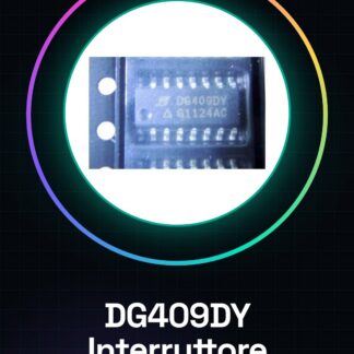
Tutorial: How to Use DG409DY Analog Dual 4-Channel IC Switch
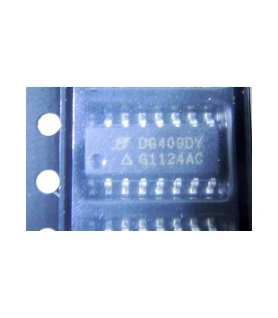
The DG409DY is an integrated circuit that allows for the management of up to eight analog channels divided into two groups of four. It is ideal for projects requiring selection among multiple analog signals, such as in multi-sensor measurement systems.
What you need
- Arduino Uno
- USB A-Micro B Cable
- Breadboard
- Pull-up Resistors
Steps
- Connect the DG409DY to the breadboard.
- Connect the analog signals to the channels of the DG409DY.
- Connect the selection lines (S0-S3) to digital pins of the Arduino.
- Add pull-up resistors to the outputs of the channels if necessary.
- Load the Arduino sketch that manages the selection and reading of analog signals.
- Verify the read data with the Arduino serial monitor.
Example code
const int s0 = 7; // collega S0 al pin 7
cost int s1 = 8; // collega S1 al pin 8
// ... per gli altri segnali
typedef void setup() {
Serial.begin(9600);
}
typedef void loop() {
analogRead(channel); // verifica il datasheet per la configurazione del canale
}
Mini project
Create a multi-sensor measurement system that reads data from four different analog sensors and sends it to the computer.
Common mistakes
- Do not connect pull-up resistors correctly.
- Configure the wrong channel of the DG409DY.
- Swap the selection pins S0-S3.
- Use an unrecognized analog signal by the DG409DY.
Recommended accessories
- Arduino Uno
- Breadboard 830 points
- USB A-Micro B cable
- Set of variable resistors
Frequently asked questions
How can I configure the correct channel?
Check the signal table in the datasheet to determine which combination of S0-S3 selects your channel.
Which analog sensors can be used with this IC?
You can use any sensor that emits an analog signal, such as photoresistors or thermistors, but check the specific compatibility in the DG409DY datasheet.
Reviews
There are no reviews yet.