 EN
 IT Italiano
 ES Español
 FR Français
 DE Deutsch
Description
What it is
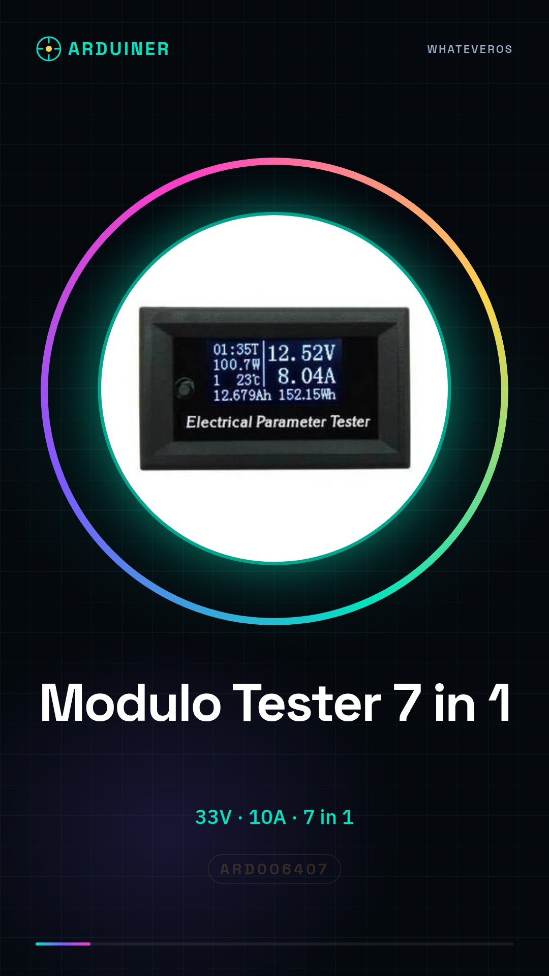
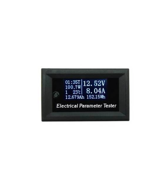
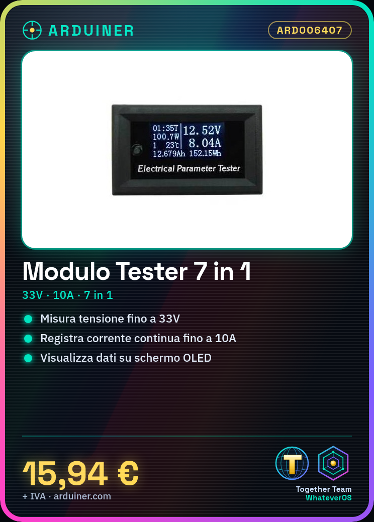
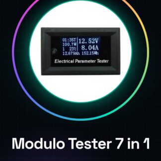
The 7-in-1 multifunction tester module with OLED display is an essential tool for makers and electronics enthusiasts who want to control and test electronic circuits. With a wide range of functionalities, this module offers a complete solution to perform various types of tests.
Features
- 7 integrated functions in a single module
- Voltmeter with a scale up to 33V
- Megohmmeter and ohmmeter
- Continuity tester
- Conductivity detector
- DC current control up to 10A
- OLED display for data visualization
What it is for
Ideally used by both beginners and experts, this tester module can be integrated with Arduino or ESP to create automatic monitoring systems. It is particularly useful for testing and verifying the proper functionality of electronic circuits.
Tutorial: How to use the 7-in-1 Multifunction Tester Module
The multifunction tester module is an essential tool for makers who want to check and test electronic circuits. With a wide range of functions, including voltage, DC and AC current, resistance, continuity, and conductivity testing, this module is ideal for both beginners and experts.
What you need
- Arduino Uno or compatible
- USB cable
- Test connection
Steps
- Connect the tester module to the Arduino’s serial port via a USB cable.
- Download and upload the provided Arduino sketch to interact with the module.
- Configure the module’s OLED interface according to your testing needs.
- Select the desired function (voltage, current, resistance, etc.) using the buttons on the module.
- Connect the component to be tested to the tester module’s connection points.
- Read and interpret the readings on the OLED screen.
- Check the accuracy of measurements by comparing them to reference tools.
- Always remember to disconnect components before changing functions.
Example code
// Includere la libreria per l'OLED
#include <Wire.h>
#include <Adafruit_SSD1306.h>
// Configurazione del modulo OLED
#define SCREEN_WIDTH 128
#define SCREEN_HEIGHT 64
Adafruit_SSD1306 display(SCREEN_WIDTH, SCREEN_HEIGHT, &Wire, -1);
void setup() {
display.begin(SSD1306_I2C_ADDRESS, Wire); // Inizializza lo schermo OLED
display.display();}
void loop() { // Ciclo principale di lettura e visualizzazione dati}
Mini project
Create an automatic monitoring system for electronic circuits. Connect the tester module to an Arduino that sends readings via WiFi or Bluetooth.
Common mistakes
- Do not upload the correct sketch to Arduino.
- Connect components without selecting the correct function.
- Omit checking the accuracy of measurements.
- Use the module in unsafe electrical conditions.
Recommended accessories
- Arduino Uno
- USB A-MicroB cable
- Test connection
- Resistors from 10 ohm to 1M ohm
Frequently asked questions
What is the maximum voltage the module can measure?
Check the datasheet.
How can I upload the sketch to Arduino?
Use the Arduino IDE and connect it via USB.
The OLED module does not turn on, what should I do?
Check the power connection and cables.
Reviews
There are no reviews yet.