 EN
 IT Italiano
 ES Español
 FR Français
 DE Deutsch
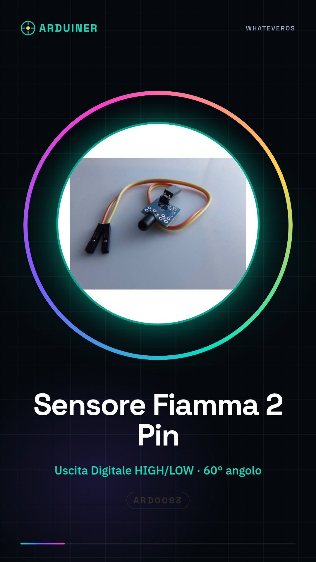
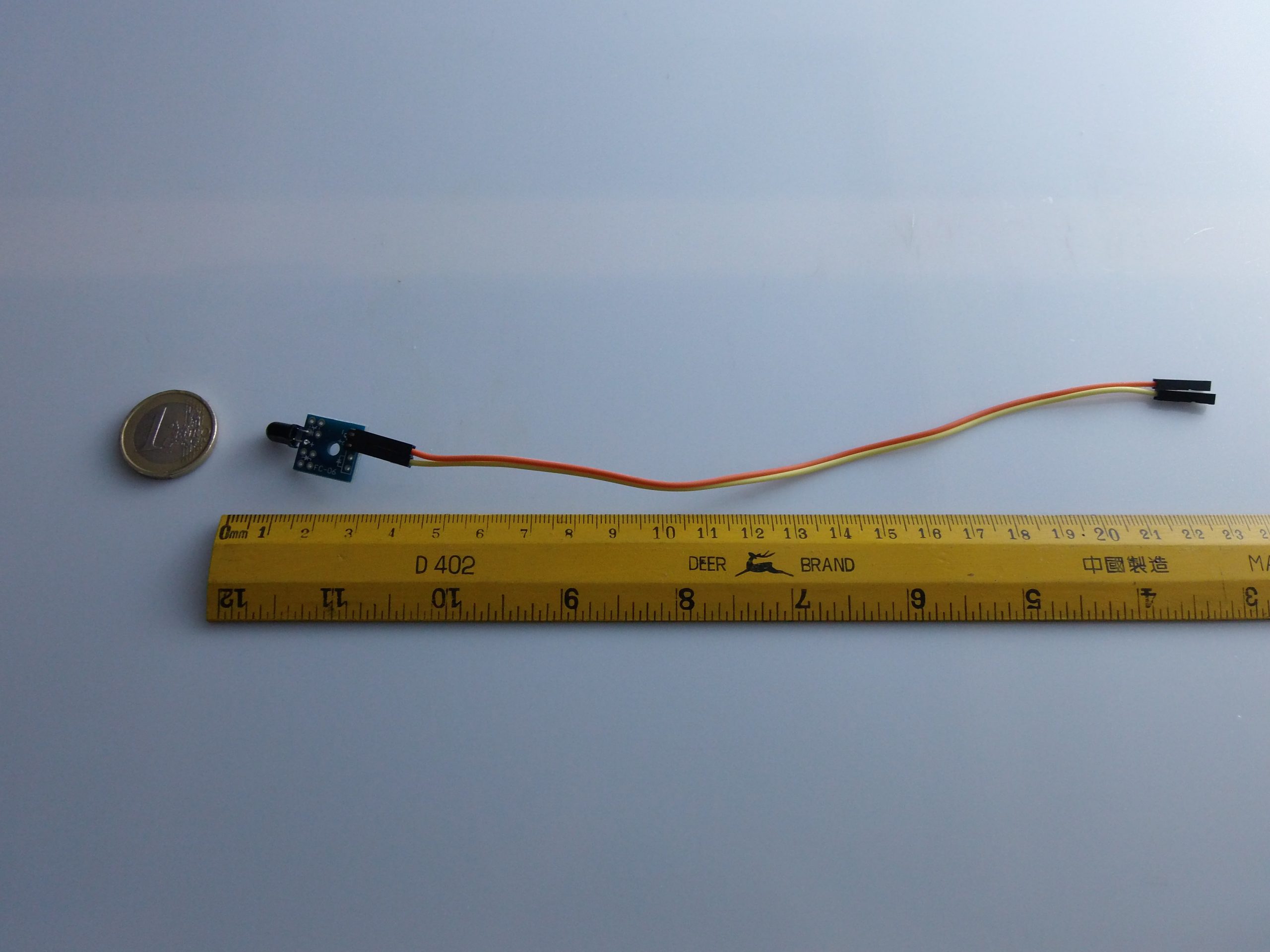
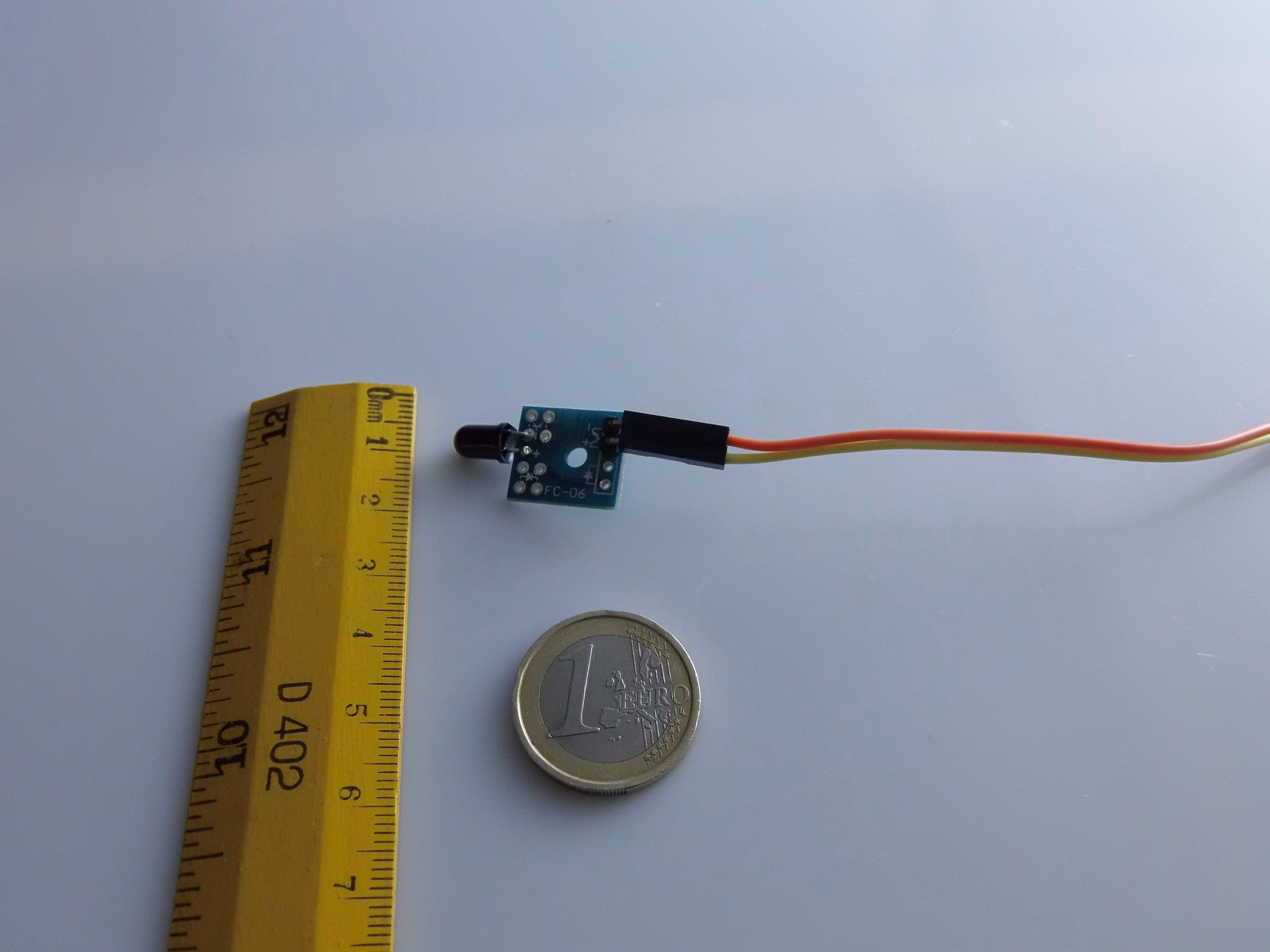
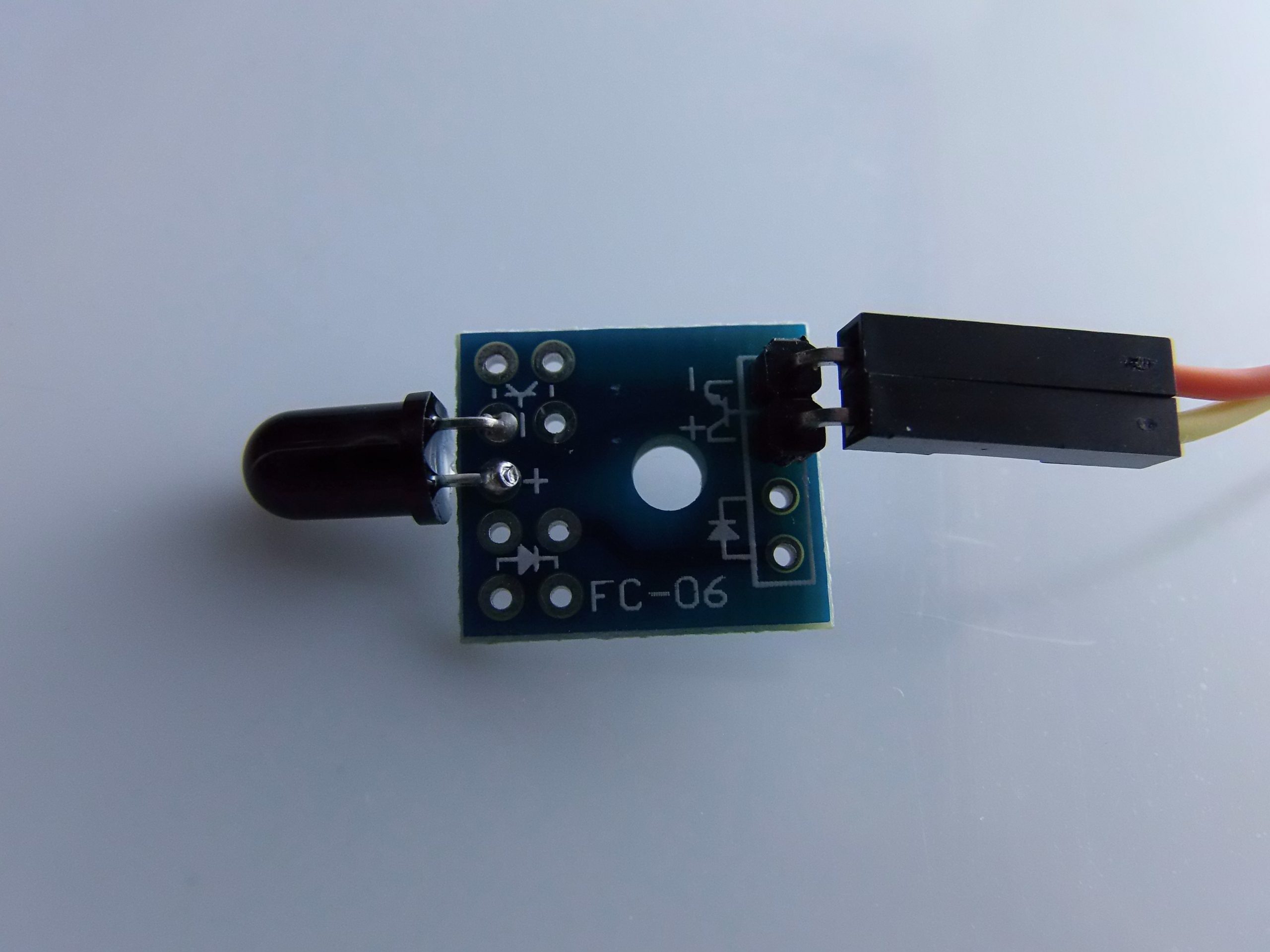
Description
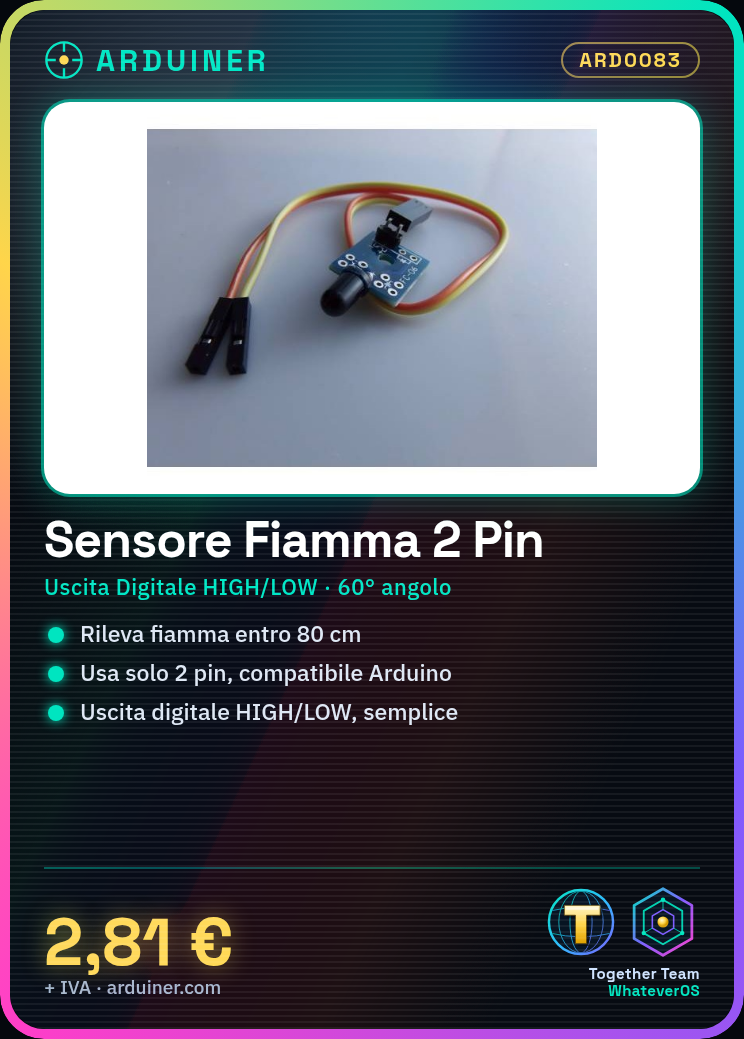
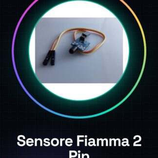
🔥 Flame Sensor – 2 Pin – Compatible with Arduino
📦 General Description
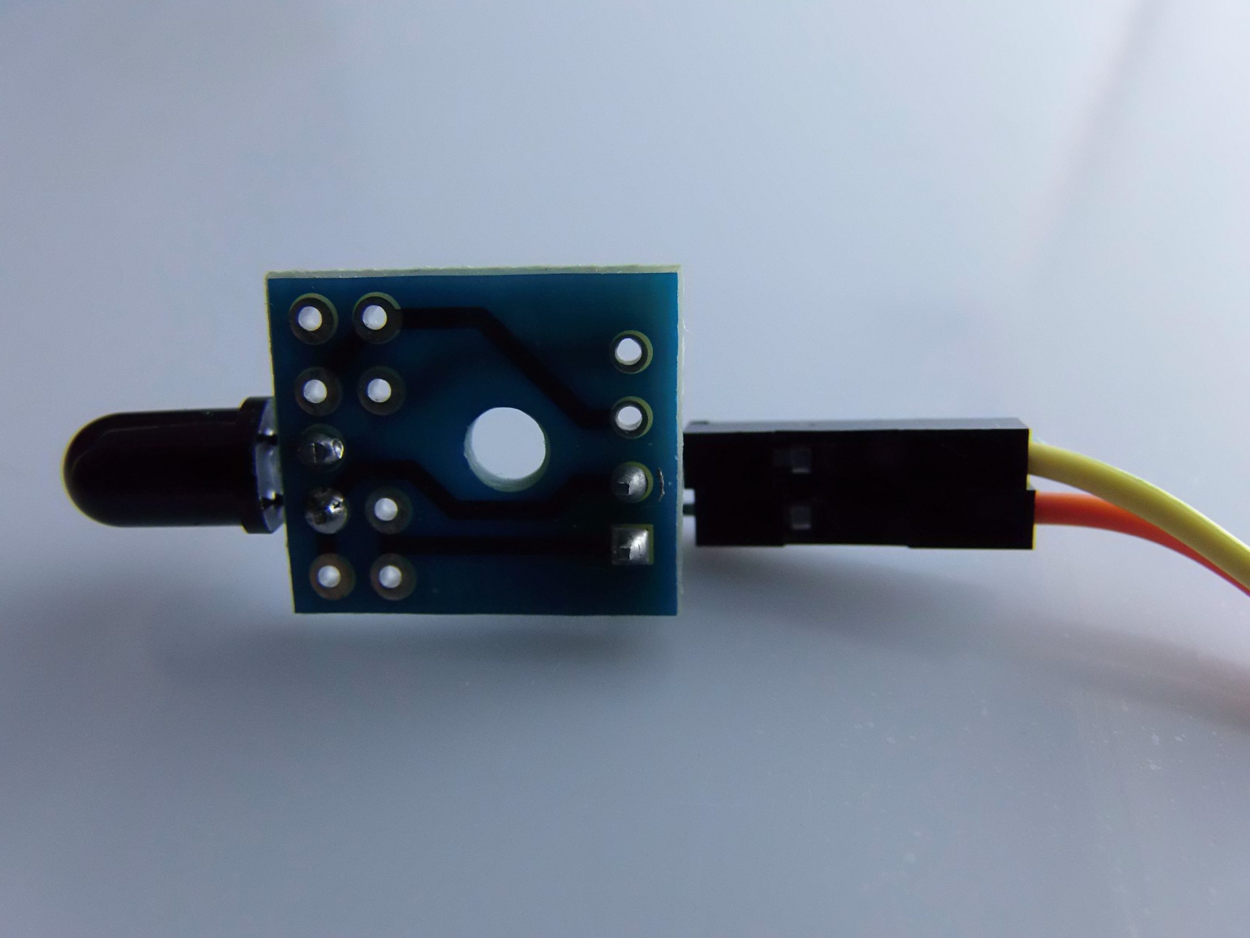
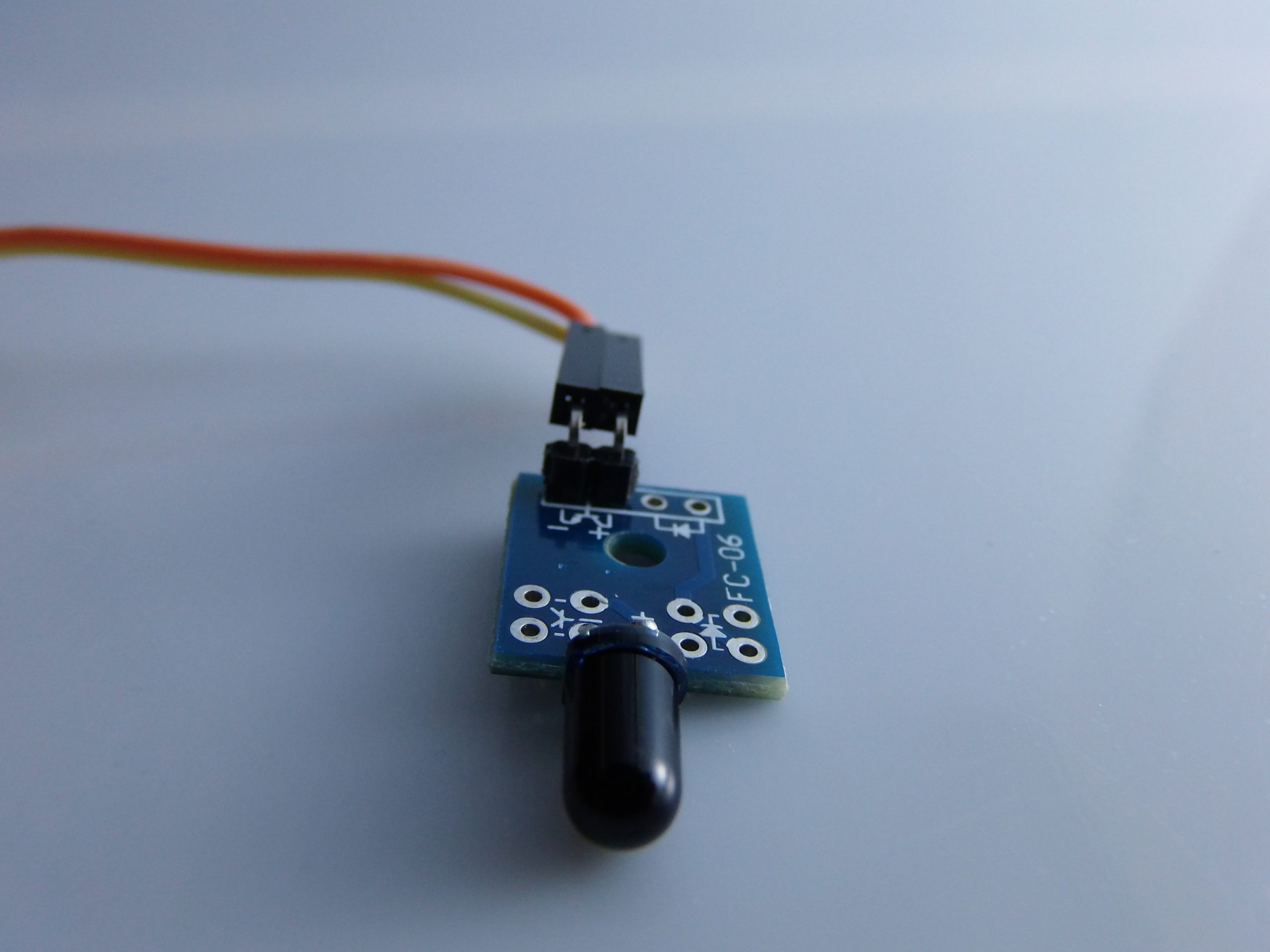
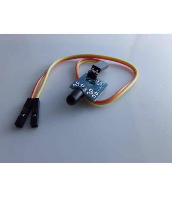
The flame sensor with 2 pins is an electronic module capable of detecting the presence of flames o light sources at high temperatures within the infrared (IR) spectral range , typically between 760 nm and 1100 nm. It is particularly useful for security projects, robotics, or fire alarm devices.
🔧 Technical Specifications
- Number of Pins: 2 (Signal, GND)
- Output Type: Digital (HIGH/LOW)
- Detection Range: up to 80 cm (depending on flame intensity)
- Detection Angle: ~60°
- Wavelength Detected: 760 nm – 1100 nm (infrared)
- Power Supply: 3.3V – 5V (compatible with Arduino)
- Compact Module: easy to integrate into embedded projects
🔌 Connection with Arduino
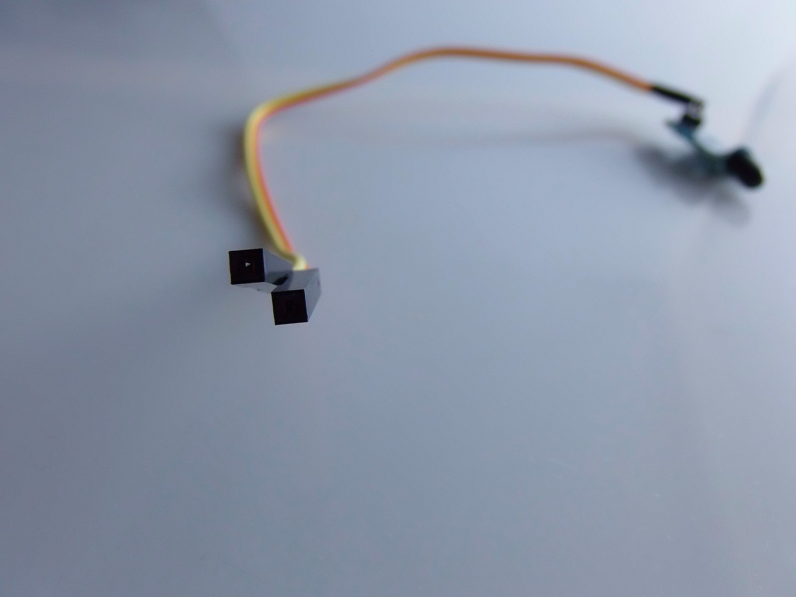
The module has 2 pins:
- Pin 1 (S) – Digital output → connect to a digital pin of Arduino (e.g., D2)
- Pin 2 (–) – GND → connect to GND of Arduino
The module does not have a separate power pin because it is often self-powered through the signal line (internal pull-up of Arduino), but in some models, a VCC pin may be present (in that case: 5V or 3.3V).
Example wiring (for an S-GND module):
| Sensor | Arduino |
|---|---|
| S | D2 |
| GND | GND |
💻 Arduino Code – Basic Example
const int flamePin = 2;  // Pin digitale collegato al sensore
const int ledPin = 13;   // LED integrato per segnalazione

void setup() {
  pinMode(flamePin, INPUT);
  pinMode(ledPin, OUTPUT);
  Serial.begin(9600);
}

void loop() {
  int flameState = digitalRead(flamePin);

  if (flameState == LOW) {  // Fiamma rilevata
    digitalWrite(ledPin, HIGH);
    Serial.println("🔥 Fiamma rilevata!");
  } else {
    digitalWrite(ledPin, LOW);
    Serial.println("✅ Nessuna fiamma");
  }

  delay(500);
}
🔍 Explanation
- The sensor returns LOW when it detects a flame (typical behavior).
- The built-in LED on the Arduino turns on in case of flame detection.
- The serial monitor displays the status every 500 ms.
🛠️ Usage Examples
- Fire Alarm: connect a buzzer or a GSM module to send an SMS in case of detection.
- Robotics: firefighting robots that seek out flames and extinguish them with a fan.
- Security systems: integration into a home automation system to cut off electrical power.
📚 Usage Tips
- Avoid direct sunlight or other IR sources (e.g., lighters, remote controls) during testing. If you want greater accuracy or range, consider a 3-pin or 4-pin flame module
- with analog output and sensitivity adjustment. 3 pin or 4 pin with analog output and sensitivity adjustment.
- You can combine multiple sensors to achieve a wider angle detection (e.g., 180° or 360°).
✅ Conclusion
The 2-pin flame sensor is a simple yet powerful component, perfect for those who want to implement flame detection with minimal hardware and software complexity. Thanks to its compatibility with Arduino, it can be easily integrated into educational, hobby, and prototyping projects.
| GENERAL | MODEL | FC 06 Infrared Flame Detection Module |
| MATERIALS | pbc + components | |
| COMPATIBILITY | ARDUINO | |
| ELECTRICAL COMPONENTS | INPUT VOLTAGE | 5V |
| WEIGHT AND DIMENSIONS | PRODUCT WEIGHT | 10g |
| PACKAGE WEIGHT | 0.2 kg | |
| PRODUCT DIMENSIONS
(L x W x H) |
24 x 1.5 x 1 cm | |
| PACKAGE DIMENSIONS
(L x W x H) |
10 x 5 x 2 cm | |
| PACKAGE CONTENT | PACKAGE CONTENT | 1 x Module |
We have datasheets available for all components, should it not be present in the product download sheet, send us a message through the contact us form and we will publish it as soon as possible on our website.
Tutorial: How to Use Flame Sensor with Arduino Compatible PCB
The Flame Sensor ARD0083 is a useful component for home security or robotics projects that require fire detection. Ideal for both beginners and more experienced makers, this sensor can be easily integrated with Arduino.
What you need
- Arduino Uno
- USB A-MicroB Cable
- Flame Sensor ARD0083
- PC with Installed Arduino IDE
Steps
- Connect the flame sensor to the Arduino digital pin using a jumper wire.
- Open the Arduino IDE and load the example sketch to read the sensor values.
- Check that the communication between the sensor and the Arduino is stable.
- Modify the sketch if necessary to adapt it to the project specifications.
- Test the system safely against a heat source.
- Optimize the detected value limits of the sensor to improve accuracy.
Example code
const int ledPin = 13;
const int flameSensorPin = 2;

void setup() {
  pinMode(ledPin, OUTPUT);
}

void loop() {
  if (analogRead(flameSensorPin) > verifica sul datasheet) {
    digitalWrite(ledPin, HIGH);
  } else {
    digitalWrite(ledPin, LOW);
  }
}
Mini project
Create a home alarm system that turns on an LED light when the presence of flames is detected.
Common mistakes
- Incorrect connection of the sensor to the Arduino pin
- Threshold values not optimized for specific conditions
- Ignore safety instructions during testing
- Do not verify hardware compatibility
Recommended accessories
- RGB LED Kit
- Arduino Buzzer
- ESP8266 Wi-Fi Module
- 16×2 LCD Display
Frequently asked questions
How can I optimize the sensor for low light conditions?
Check the datasheet for the sensor specifications and adjust the threshold values in the code accordingly.
Does the sensor work in the presence of smoke?
Check the datasheet to see if the sensor is designed to detect both flames and smoke.
Reviews
There are no reviews yet.