 EN
 IT Italiano
 ES Español
 FR Français
 DE Deutsch
Description
Technical Description
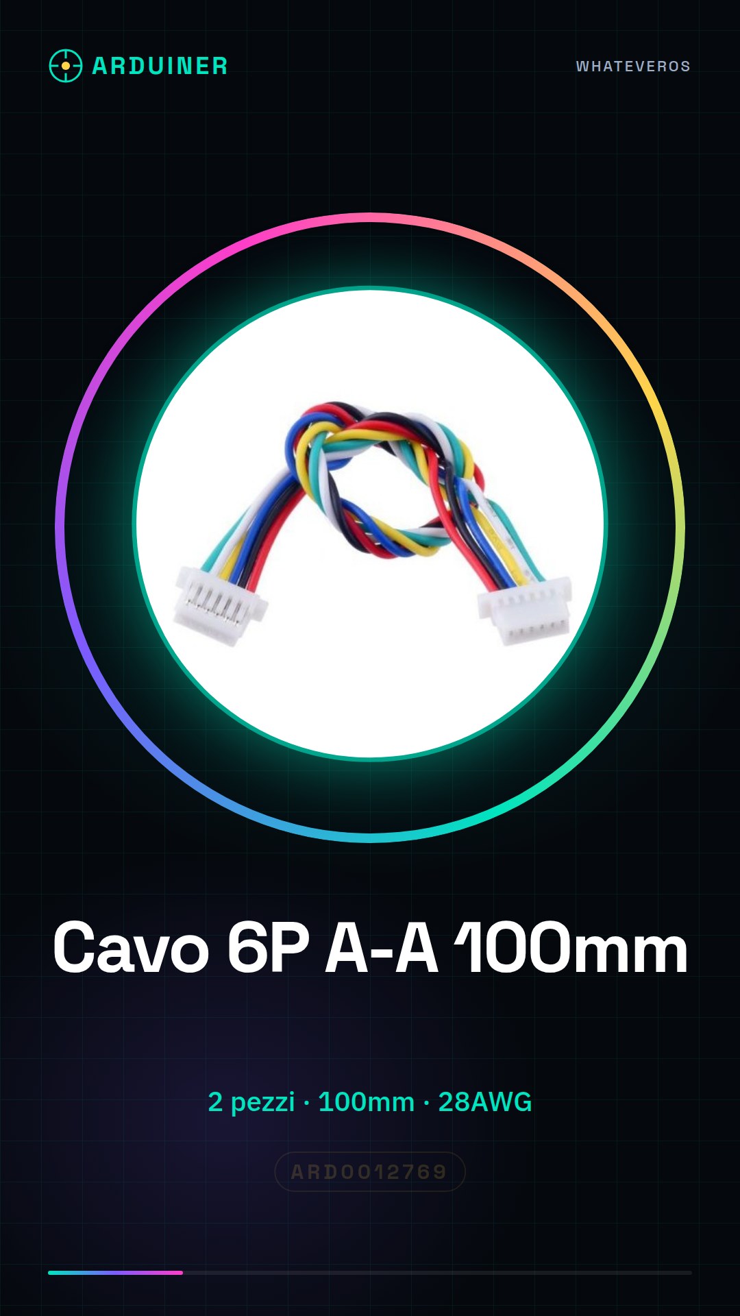
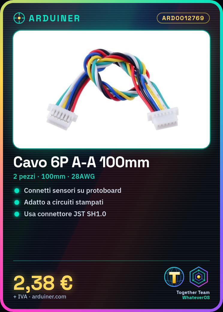
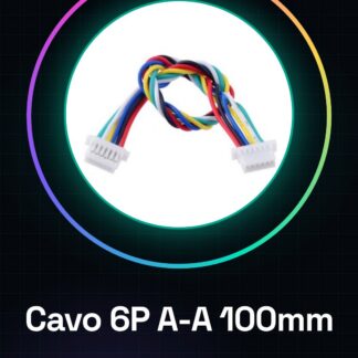
The product is a 6P A-A cable with a length of 100mm and JST SH1.0 connectors, made with 28AWG wire. This type of cable is used to connect electronic components to each other, ensuring a stable and precise connection. It is suitable for building circuits on protoboards or printed circuit boards.
The JST SH1.0 cable is designed to safely and reliably connect modules and sensors, allowing connections between various electronic devices. Its reduced length and reduced diameter make it suitable for applications where cable clutter needs to be minimized.
To use this cable, it must be connected to the JST SH1.0 connectors present on electronic modules or sensors. It is important to verify the correct position of the contacts before applying power to the circuit.
Key Specifications
| Parameter | Value |
| Model | 6P A-A 100MM SH 1.0 JST |
| Quantity | 2 pieces |
| Wire Gauge | 28AWG |
| Connector Type | SH1.0 JST |
| Length | 100mm |
| Voltage | N/D (see manufacturer’s datasheet) |
| Current | N/D (see manufacturer’s datasheet) |
| Container | N/D (see manufacturer’s datasheet) |
Installation and Usage
- Ensure that the cables have a straight and clean cut.
- Identify the correct pins on both SH1.0 JST connectors.
- Connect the wires to the correct pins, ensuring that the contacts are properly positioned.
- Check the wire connections to ensure there are no incorrect connections.
- Check the datasheet for voltage and current specifications.
Compatibility and Requirements
- This cable is compatible with modules and sensors featuring JST SH1.0 connectors.
- A multimeter is required to verify the correct connection.
- It is recommended to use a printed circuit board or a protoboard to build the circuit.
Limitations and Important Notes
- The cable is not designed for long-distance connections.
- It is important to verify compatibility with JST SH1.0 connectors.
- Maximum voltage and current limits must be adhered to in order to prevent component damage.
- Do not use cutting tools unsuitable for a clean cut.
Troubleshooting
Incorrect Connections
Probable cause: The wires were connected to incorrect pins.
Solution: Check the contact position and connect the wires to the correct pins.
Loose connections
Probable cause: The wires were not connected properly.
Solution: Check the wire connections and ensure that the contacts are in good position.
Damaged wire
Probable cause: The wire was cut with inappropriate tools.
Solution: Cut the wire with appropriate cutting tools for a clean cut.
Not working
Probable cause: The voltage or current does not meet the specifications.
Solution: Check the voltage and current specifications on the datasheet and adhere to them.
Use cases
Temperature sensor
Objective: Connect a temperature sensor to a detection module.
What is needed: 6P A-A 100MM SH 1.0 JST 28AWG wire, temperature sensor, detection module.
Steps: 1) Verify the compatibility of the sensor and module with JST SH1.0 connectors. 2) Connect the sensor to the module using the cable. 3) Check the connection with a multimeter. 4) Install the circuit on a protoboard.
Expected result: The temperature sensor is correctly connected to the detection module.
Power Supply Circuit
Objective: Create a simple power supply circuit for an LED.
What you need: 6P A-A 100MM SH 1.0 JST 28AWG cable, LED, power supply module.
Steps: 1) Verify the compatibility of the power supply module with JST SH1.0 connectors. 2) Connect the power supply module to the LED using the cable. 3) Check the connection with a multimeter. 4) Install the circuit on a protoboard.
Expected result: The LED is correctly powered by the power supply module.
Control Circuit
Objective: Connect a control module to a motor.
What is needed: 6P A-A 100MM SH 1.0 JST 28AWG cable, control module, motor.
Steps: 1) Check the compatibility of the control module and motor with JST SH1.0 connectors. 2) Connect the control module to the motor using the cable. 3) Verify the connection with a multimeter. 4) Install the circuit on a protoboard.
Expected result: The control module is correctly connected to the motor.
Detection circuit
Objective: Connect a light sensor to a detection module.
What is needed: 6P A-A 100MM SH 1.0 JST 28AWG cable, light sensor, detection module.
Steps: 1) Check the compatibility of the light sensor and detection module with JST SH1.0 connectors. 2) Connect the light sensor to the module using the cable. 3) Verify the connection with a multimeter. 4) Install the circuit on a protoboard.
Expected result: The light sensor is correctly connected to the detection module.
Protection circuit
Objective: Connect a protection module to a circuit.
What’s needed: 6P A-A 100MM SH 1.0 JST 28AWG cable, protection module.
Steps: 1) Check the compatibility of the protection module with JST SH1.0 connectors. 2) Connect the protection module to the circuit using the cable. 3) Verify the connection with a multimeter. 4) Install the circuit on a protoboard.
Expected result: The protection module is correctly connected to the circuit.
Temperature control circuit
Objective: Connect a temperature sensor to a control module.
What’s needed: 6P A-A 100MM SH 1.0 JST 28AWG cable, temperature sensor, control module.
Steps: 1) Verify the compatibility of the temperature sensor and the control module with JST SH1.0 connectors. 2) Connect the temperature sensor to the module using the cable. 3) Check the connection with a multimeter. 4) Install the circuit on a protoboard.
Expected result: The temperature sensor is correctly connected to the control module.
Light control circuit
What you need: 6P A-A 100MM SH 1.0 JST 28AWG cable, light sensor, control module.
Steps: 1) Verify the compatibility of the light sensor and the control module with JST SH1.0 connectors. 2) Connect the light sensor to the module using the cable. 3) Check the connection with a multimeter. 4) Install the circuit on a protoboard.
Expected result: The light sensor is correctly connected to the control module.
Motors control circuit
What’s needed: 100MM SH 1.0 JST 28AWG 6P A-A cable, control module, motor.
Steps: 1) Check the compatibility of the control module and motor with JST SH1.0 connectors. 2) Connect the control module to the motor using the cable. 3) Verify the connection with a multimeter. 4) Install the circuit on a protoboard.
Expected result: The control module is correctly connected to the motor.
In the package
- 2 pieces
Complete the project
- 2 pieces 100MM SH 1.0 JST 28AWG 6P A-B cable with SH1.0 connector: These cables are compatible with JST SH1.0 connectors and can be used to connect different modules and sensors.
- 2 pieces 100MM SH 1.0 JST 28AWG 9P A-B cable with SH1.0 connector: These cables are useful for creating secure and precise connections between various electronic components.
Technical FAQs
How can I verify the cable connections?
Use a multimeter to check the grip of the wires.
Which specifications should I verify on the datasheet?
Check the maximum voltage and maximum current.
Can I use these wires with different connectors?
Check compatibility with JST SH1.0 connectors.
How can I cut the wires cleanly?
Use cutting tools suitable for a clean cut.
Tutorial: How to use 6P A-A 100MM SH 1.0 JST 28AWG Wires
These wires are ideal for connecting sensors, electronic modules, and other components on a protoboard or printed circuit board. Useful for beginner and intermediate makers.
What you need
- 2 pieces 6P A-A 100MM SH 1.0 JST 28AWG Wire
- JST SH1.0 connector
- Printed circuit board or protoboard
- Cutting tools
Steps
- 1. Make sure the wires have a straight and clean cut.
- 2. Identify the correct pins on both JST SH1.0 connectors.
- 3. Connect the wires to the correct pins, ensuring that the contacts are properly positioned.
- 4. Check the wire connections to ensure there are no incorrect connections.
- 5. Verify the voltage and current specifications on the datasheet.
- 6. Test the connection with a multimeter to verify the correct connection.
- 7. Install the wires on a printed circuit board or protoboard.
- 8. Check the stability of the connections before applying voltage.
Mini project
Build a simple power circuit for an LED using a JST SH1.0 as power supply and a 6P A-A cable to connect the LED.
Common mistakes
- Do not check the wire connections before applying voltage.
- Connect the wires to the wrong pins on the JST connector.
- Ignore the voltage and current specifications on the datasheet.
- Do not use cutting tools for a clean cut.
Recommended accessories
- JST SH1.0 connector
- Multimeter
- Printed circuit boards or protoboard
- Cutting tools
Frequently asked questions
How can I check the grip of the cables?
Use a multimeter to check the grip of the cables.
Which specifications should I verify on the datasheet?
Check the maximum voltage and maximum current.
Can I use these cables with different connectors?
Check compatibility with JST SH1.0 connectors.
How can I cut the cables cleanly?
Use specific cutting tools to avoid damage to the cables.
Reviews
There are no reviews yet.