 EN
 IT Italiano
 ES Español
 FR Français
 DE Deutsch
Description
Technical Description
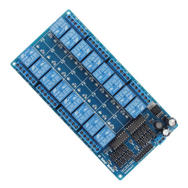
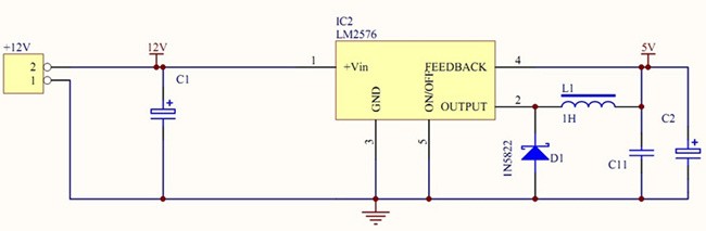
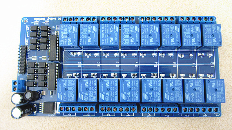
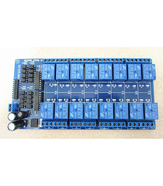
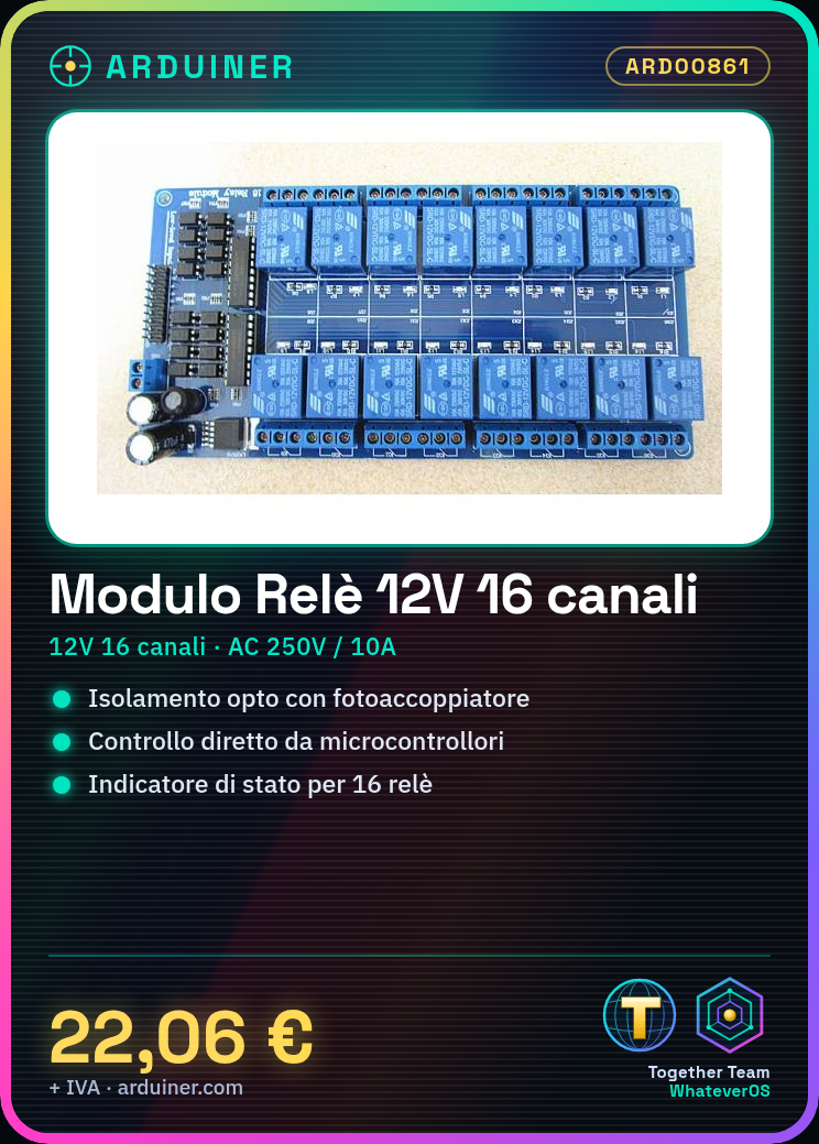
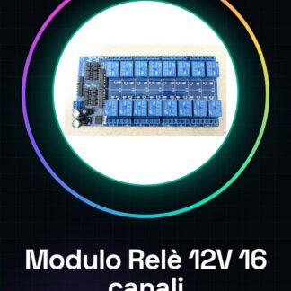
The 12V 16 Channel Relay Module with Isolated Optocoupler Protection and LM2576 Chip is a component used for managing electrical circuits in electronic automation projects. The module allows the control of electrical devices through a microcontroller, providing isolation between the control circuit and the power circuit. The module supports operating voltages of 5V and 12V and features an LM2576 chip for voltage regulation. Each relay can handle currents up to 10A in both DC and AC.
The presence of opto-isolators on each channel ensures electrical isolation between the input and output, protecting the control circuit from potential electronic interference. The LED indicator for each relay provides immediate visualization of the relay’s activation or deactivation status. The module is designed to be easily installed on a breadboard or PCB, with holes for mounting screws.
The module is suitable for projects that require the management of electrical devices from a microcontroller, such as the regulation of lights, motors, and other electrical loads. Its modular configuration allows for the addition of additional modules to increase the capacity for managing electrical devices.
Key Specifications
| Parameter | Value |
| Model | 12V 16-Channel Relay Module |
| Number of Channels | 16 |
| Operating Voltage | 5V, 12V |
| Control Voltage | 3,3V / 5V |
| Trigger Current | 3mA |
| Maximum Load | AC 250V / 10A, DC 30V / 10A |
| Regulator Chip | LM2576 |
| Control Interface | Microcontroller (8051, AVR, PIC, PLC, DSP, ARM, MSP430, TTL Logic) |
| Status Indicator | LED for each relay |
| Dimensions | 178 * 90 * 20 mm |
| Enclosure | N/D (see manufacturer’s technical sheet) |
Installation and Usage
- Connect the relay module to the microcontroller or control circuit using the available connectors.
- Select the module’s power supply voltage (5V or 12V) based on project requirements.
- Connect the power supply voltage to the module based on the selected voltage.
- Connect the control commands to the module’s input pins.
- Perform an initial test by turning the relays on and off to verify proper operation.
Compatibility and Requirements
- The module is compatible with microcontrollers such as 8051, AVR, PIC, PLC, DSP, ARM, MSP430, and TTL logic.
- It can be used with electronic control systems that support 3.3V or 5V control voltages.
- The module can be used in combination with other relay modules to increase the capacity to manage electrical loads.
Limitations and Important Notes
- The module is not designed for managing electrical loads directly without electrical isolation.
- It is necessary to verify the compatibility of the power supply and control voltages with the module.
- Using adequate electrical isolation is recommended to protect the control circuit.
- The module does not include physical connectors for power supply and control, which must be provided separately.
Troubleshooting
Relays do not activate.
Probable cause: Incorrect connection or insufficient control voltage.
Solution: Check connections and control voltage.
The status LEDs do not light up.
Probable cause: Power or control issues.
Solution: Check power voltage and control connections.
The module does not respond to control commands.
Probable cause: Communication problems between the microcontroller and the module.
Solution: Check microcontroller configuration and connections.
The relays activate and deactivate uncontrollably.
Probable cause: Electronic interference or power issues.
Solution: Check electrical insulation and power supply voltage stability.
Use cases
Home lighting system
Objective: Adjust light intensity based on natural light.
What is needed: 12V 16-channel relay module.
Steps: 1) Install the relay module. 2) Connect the light sensors. 3) Configure the microcontroller to adjust the light intensity.
Expected result: The system adjusts the light intensity based on natural light.
Automatic irrigation system
Objective: Regulate irrigation based on soil conditions.
What you need: 12V 16-channel relay module.
Steps: 1) Install the relay module. 2) Connect the moisture sensors. 3) Configure the microcontroller to regulate irrigation.
Expected result: The system regulates irrigation based on soil conditions.
Home security system
Objective: Regulate the activation of sirens and security lights.
What you need: 12V 16-channel relay module.
Steps: 1) Install the relay module. 2) Connect the motion sensors. 3) Configure the microcontroller to regulate the activation of sirens and lights.
Expected result: The system regulates the activation of sirens and security lights based on motion sensors.
Motors Control System
Objective: Regulate the speed of industrial motors.
What’s needed: 12V 16-channel relay module.
Steps: 1) Install the relay module. 2) Connect the speed sensors. 3) Configure the microcontroller to regulate the speed of the motors.
Expected result: The system regulates the speed of industrial motors based on speed sensors.
Door and Window Control System
What’s needed: 12V 16-channel relay module.
Steps: 1) Install the relay module. 2) Connect the opening sensors. 3) Configure the microcontroller to regulate the opening and closing of doors and windows.
Expected result: The system regulates the opening and closing of doors and windows based on opening sensors.
Heating System Control System
What is needed: 12V 16 Channel Relay Module.
Steps: 1) Install the relay module. 2) Connect the temperature sensors. 3) Configure the microcontroller to regulate heating.
Expected result: The system regulates heating based on weather conditions.
Refrigeration System Control System
What is needed: 12V 16 Channel Relay Module.
Steps: 1) Install the relay module. 2) Connect the temperature sensors. 3) Configure the microcontroller to regulate cooling.
Expected result: The system regulates cooling based on weather conditions.
Ventilation System Control
What is needed: 12V 16 Channel Relay Module.
Steps: 1) Install the relay module. 2) Connect the air quality sensors. 3) Configure the microcontroller to regulate ventilation.
Expected result: The system adjusts the ventilation based on air quality conditions.
In the package
- 1 piece
Complete the project
- SRD-12VDC-SL-C Songle Relay T73-12V 5pin: For managing electrical devices with voltages below 12V.
Technical FAQs
Why don’t the relays activate?
Check the connections and control voltage.
Why don’t the status LEDs light up?
Check the power supply voltage and control connections.
How can I configure the microcontroller to control the relays?
Configure the microcontroller’s control pins to send activation commands to the relays.
Which power supply voltages are supported?
The module supports power supply voltages of 5V and 12V.
Tutorial: How to use 12V 16 Channel Relay Module
The 12V 16 Channel Relay Module is a fundamental component for projects requiring the control of electrical devices by an Arduino. Ideal for beginners and intermediates, it allows you to control barcode readers, light bulbs, or any other high-consumption device.
What you need
- Arduino Uno or compatible
- USB cable
- separate 12V power supply
- connectors for the relays
Steps
- Connect the module’s power supply (VIN and GND) to an external 12V power adapter.
- Connect the Arduino module to the computer via USB.
- Check the data pin connections between Arduino and relays (D0-D15).
- Upload the example sketch to the Arduino to test the relays.
- If necessary, modify the sketch to suit your needs.
- Test the relay functionality with the Serial Monitor software.
- Verify that each relay operates correctly.
- Remember to protect sensitive circuits from overheating.
Example code
void setup() {
  for (int i = 0; i < 16; i++) {
    pinMode(i, OUTPUT);
  }
}

void loop() {
  for (int i = 0; i < 16; i++) {
    digitalWrite(i, HIGH);
    delay(500);
    digitalWrite(i, LOW);
    delay(500);
  }
}
Mini project
Create a home heating control system with 4 relays to manage radiators in different rooms.
Common mistakes
- Connect the module to voltages below 12V.
- Do not protect the Arduino from external circuits.
- Use unsuitable connectors.
- Ignore the datasheet documentation for specific pins.
Recommended accessories
- Separate 12V power supply
- USB A/B cable
- Electronic protection connector
- 3D printed case for the module
Frequently asked questions
How much current can each relay handle?
Check the datasheet.
Can I use this module with Arduino Mega?
Yes, but make sure to connect the data pins correctly.
What does optoisolated mean?
Protects the Arduino from potential electrical damage from external circuits.
Reviews
There are no reviews yet.