 EN
 IT Italiano
 ES Español
 FR Français
 DE Deutsch
Description
What it is
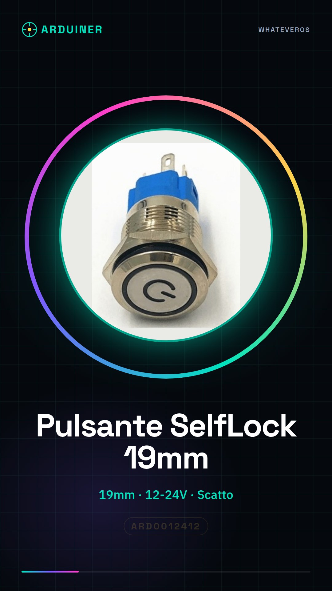
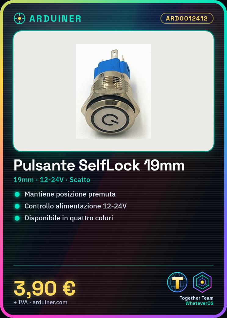
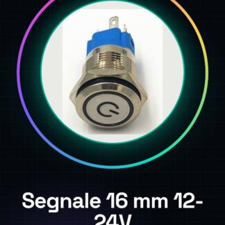
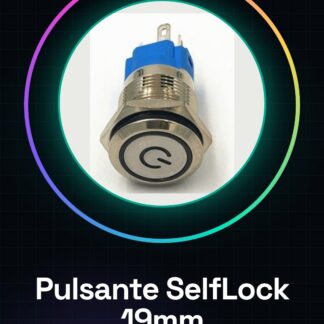
The SelfLock 19mm power supply signal with push button snap switch is an electronic component designed to monitor and control power supply in various projects. This SelfLock button features a snap switch that maintains the pressed position until manually released, making it ideal for implementing safety or timed lockout functions.
Features
- Dimensions: 19mm
- Operating voltage range: 12-24V
- Button color: Red, Green, Blue, Yellow
- Type: SelfLock push button snap switch
What it is for
This SelfLock button is suitable for beginner and intermediate makers working with Arduino or other microcontrollers. It can be used to create home security systems, activating an alarm when the button is pressed and blocking access until it is released. Additionally, it is compatible with a wide range of electronic projects that require safe and reliable power control.
Tutorial: How to use SelfLock Button 19mm 12-24V
This SelfLock button is ideal for implementing safety interruption or timed lockout functions in electronic projects. It is suitable for beginner and intermediate makers working with Arduino or other microcontrollers.
What you need
- Arduino or compatible microcontroller
- Jumper wire
- Power supply connection 12-24V
- Ground connection
- Pull-up resistor (check datasheet)
- Arduino development software
Steps
- Connect the SelfLock button to the microcontroller using jumper wires.
- Check the polarity of the button: the positive pole is usually red, the negative is black (check the datasheet).
- Connect the positive pole of the button to the input pin of the microcontroller.
- Connect the negative pole of the button to GND.
- Connect a pull-up resistor between the input pin and VCC (check the datasheet).
- Write and upload an Arduino sketch to read the state of the button.
- Test the button by pressing and releasing it to verify that the microcontroller correctly detects state changes.
- Configure the button for timed lockout or safety interlock mode.
Example code
const int pulsantePin = 2; // Collega il pulsante al pin 2
int statoPulsante = LOW;
void setup() {
  pinMode(pulsantePin, INPUT_PULLUP);
  Serial.begin(9600);
}
void loop() {
  statoPulsante = digitalRead(pulsantePin);
  Serial.println(statoPulsante);
  delay(100);
}
Mini project
Create a home security system that activates an alarm when the SelfLock button is pressed and locks access until it is released.
Common mistakes
- Do not connect the pull-up resistor correctly.
- Do not check the polarity of the button.
- Do not test the button before integrating it into the project.
- Do not configure the button correctly for the timed lockout mode.
Recommended accessories
- Variable resistors
- LCD display modules
- Audible alarms
- Wireless communication modules
Frequently asked questions
What is the difference between the colors of the buttons?
Colors indicate different operational states or error states.
Can I use this button with a Raspberry Pi?
Yes, but an external pull-up resistor may be necessary.
What is the duration of the timed lockout?
Check the product specification on the datasheet.
Reviews
There are no reviews yet.