 EN
 IT Italiano
 ES Español
 FR Français
 DE Deutsch
Description
Technical Specifications
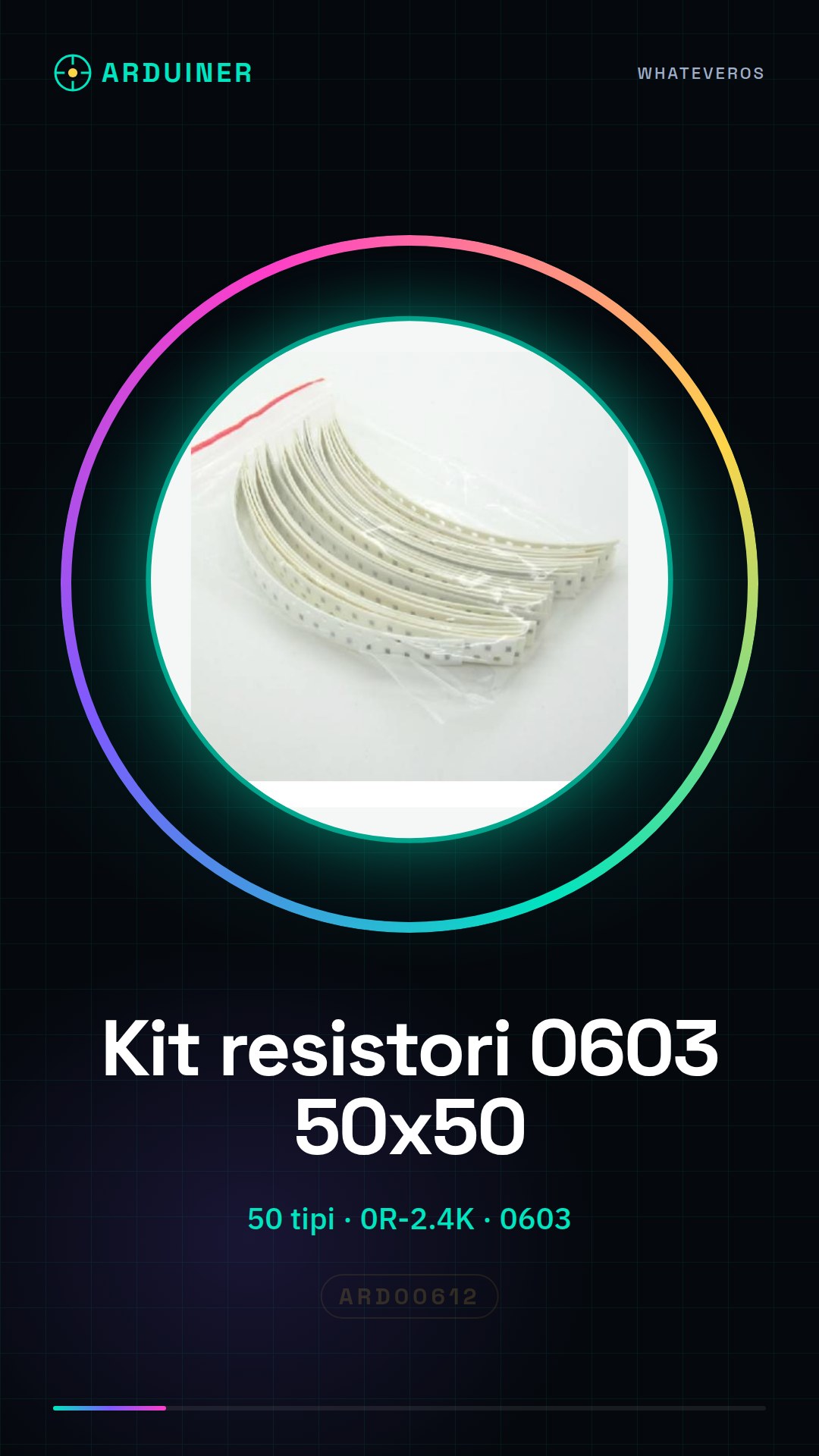
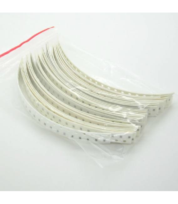
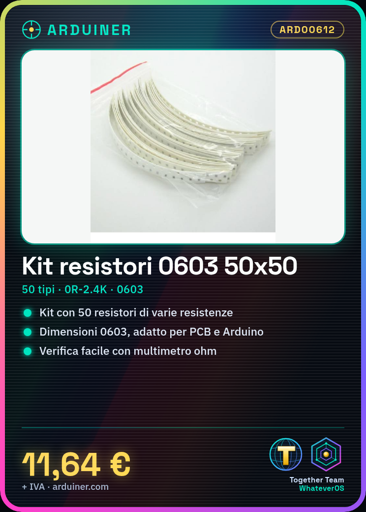
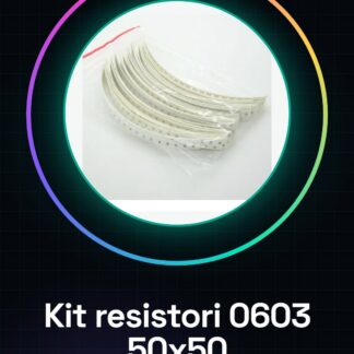
The 0603 Resistor Kit, 0R-2.4K, 50 pieces of 50 types, is a set of electronic components useful for prototyping and testing projects. This kit contains a variety of resistance values, from 0 ohms to 2.4 kiloohms, in SMD 0603 format, making it suitable for applications on small PCBs. SMD resistors are used to limit the flow of electrical current in electronic circuits, regulating the brightness of LEDs, the operation of integrated circuits, and other functions.
The resistance of an electronic component is determined by the material and geometry of the component. SMD 0603 resistors are small and light, but offer stable and reliable resistance. Their small size makes them suitable for projects that require a high degree of integration and miniaturization.
For installation, a SMD printer is required to correctly position the components on the PCB, followed by a low-temperature soldering iron or an SMD rework station to secure the components. Checking the resistance value with a multimeter is crucial before using the component in the circuit.
Key Specifications
| Parameter | Value |
| Model | 0603 Resistor Kit, 0R-2.4K |
| Quantity | 50 pieces |
| Values | 0R, 130?, 150?, 160?, 180?, 200?, 220?, 240?, 270?, 300?, 330?, 360?, 1?, 390? |
| Dimensions | 0603 |
| Container | Pack of 50 pieces |
Installation and Usage
- Check the desired resistance value on the datasheet.
- Set the SMD printer for 0603 dimensions.
- Place the resistors on the PCB using the SMD printer.
- Secure the components with a low-temperature soldering iron or in an SMD rework station.
- Check the resistance value with a multimeter.
Compatibility and Requirements
- This kit of SMD 0603 resistors is compatible with Arduino projects and PCBs.
- It is suitable for beginners and experts in electronic prototyping.
- An Arduino Uno, an SMD printer, a low-temperature soldering iron or an SMD rework station, and a multimeter are required to use it.
Limitations and Important Notes
- These resistors cannot be used for applications requiring resistance values higher than 2.4 kiloohms.
- It is important to verify the resistance value before installation.
- Avoid using excessively high reflow soldering temperatures.
- Ensure that SMD components are correctly positioned on the PCB.
Troubleshooting
The resistor does not have the expected value.
Probable cause: The resistor may be damaged or not positioned correctly.
Solution: Check the value of the resistor with a multimeter and replace the resistor if necessary.
The SMD component is not positioned correctly on the PCB layout.
Probable cause: The SMD printer might not be configured correctly.
Solution: Check the SMD printer configuration and ensure it is set for 0603 size.
The SMD component disconnects during reflow.
Probable cause: The reflow temperature might be too high.
Solution: Use a low-temperature soldering iron or a reduced-temperature SMD reflow station.
The circuit does not work as expected.
Probable cause: The resistor might be incorrectly connected or does not have the correct value.
Solution: Check the connection and the value of the resistor with a multimeter.
Use cases
Distance sensor for a robot
Objective: Adjust the sensitivity of the distance sensor.
Required: Resistor Kit 0603, 0R-2.4K
Steps: 1) Check the desired resistance value on the datasheet. 2) Position the resistor on the PCB of the distance sensor. 3) Solder the resistor with a low-temperature soldering iron. 4) Verify the resistance value with a multimeter.
Expected Result: The distance sensor functions correctly with the adjusted sensitivity.
LED Brightness Adjustment
Objective: Adjust the brightness of an LED using a potentiometer.
Required: Resistor Kit 0603, 0R-2.4K
Steps: 1) Check the desired resistance value on the datasheet. 2) Connect the resistor between the potentiometer and the LED. 3) Verify the resistance value with a multimeter.
Expected Result: The brightness of the LED can be correctly adjusted.
Motherboard Test Project
Objective: Test the pull-up resistor value of an input pin.
Required: 0603 Resistor Kit, 0R-2.4K
Steps: 1) Check the desired resistor value on the datasheet. 2) Connect the resistor between the input pin and the power supply. 3) Verify the resistor value with a multimeter.
Expected Result: The input pin functions correctly with the pull-up resistor.
Audio Amplification Board Test Project
Objective: Adjust the volume level.
Required: 0603 Resistor Kit, 0R-2.4K
Steps: 1) Check the desired resistor value on the datasheet. 2) Connect the resistor between the amplifier and the volume control. 3) Verify the resistor value with a multimeter.
Expected Result: The volume level can be adjusted correctly.
Temperature Control Board Test Project
Objective: Adjust the sensitivity of the temperature sensor.
Required: Resistor Kit 0603, 0R-2.4K
Steps: 1) Check the desired resistance value on the datasheet. 2) Connect the resistor between the temperature sensor and the control circuit. 3) Verify the resistance value with a multimeter.
Expected Result: The sensitivity of the temperature sensor can be correctly adjusted.
Light Control Board Test Project
Objective: Adjust the brightness of an LED.
Required: Resistor Kit 0603, 0R-2.4K
Steps: 1) Check the desired resistance value on the datasheet. 2) Connect the resistor between the light control and the LED. 3) Verify the resistance value with a multimeter.
Expected Result: The brightness of the LED can be correctly adjusted.
Motors Control Board Test Project
Objective: Adjust the motor speed.
What’s needed: Resistor Kit 0603, 0R-2.4K
Steps: 1) Check the desired resistance value on the datasheet. 2) Connect the resistor between the motor control and the input port. 3) Verify the resistance value with a multimeter.
Expected result: The motor speed can be correctly adjusted.
Fan control board test project
Objective: Adjust the fan speed.
What’s needed: Resistor Kit 0603, 0R-2.4K
Steps: 1) Check the desired resistance value on the datasheet. 2) Connect the resistor between the fan control and the input port. 3) Verify the resistance value with a multimeter.
Expected result: The fan speed can be correctly adjusted.
In the package
- 50 pieces of 50 types
Complete the project
- Kit resistors 1206, 0R-3.6K, 50 pieces from 50 types: 130?, 150?, 160?, 180?, 200?, 220?, 240?, 270?, 300?, 330?, 360?, 1?: For projects requiring larger size resistors.
- 1% 0805 resistor SMD kit, 0R-3.6K, 50 pieces from 50 types: 130? 150? 160? 180? 200? 220? 240? 270? 300? 330? 360? 1? 39: For projects requiring resistors with higher precision tolerance.
- Metal film resistor kit 1%, 82K-1M, 10 pieces from 24 types: 75K, 82K, 91K, 100K, 120K, 150K, 180K, 200K, 220K, 240K, 270K: For projects requiring resistors with higher resistance values.
- Colored band 1/4 w resistor kit 75k-2.2M, 10 pieces from 21 types: 75K 91K 100K 120K 150K 180K 200K 220K 240K 270K 300K 330K 390: For projects requiring resistors with higher resistance values.
- Kit resistors 0805, 3.9K-62K, 10 pieces from 21 types: 3.9K 4.7K 5.1K 5.6K 6.2K 9.1K 10K 12K 15K 18K 20K 22K 27K 30K: For projects requiring resistors with higher resistance values.
Technical FAQ
What is the minimum and maximum resistance in the kit?
0R (short circuit) – 2.4KΩ
How can I verify the resistance value?
Use a multimeter in ohm mode.
What are the soldering temperature limits?
Avoid using excessively high soldering temperatures.
What resistance values are available?
0R, 130?, 150?, 160?, 180?, 200?, 220?, 240?, 270?, 300?, 330?, 360?, 1?, 390?
Tutorial: How to use SMD 0603 Resistor Kit
SMD resistor kit for Arduino and PCB projects. For beginners and experts.
What you need
- Arduino Uno
- SMD Printer
- Multimeter
Steps
- Check the desired resistance value on the datasheet.
- Set the SMD printer for 0603 size.
- Place the resistors on the PCB using the SMD printer.
- Solder the components using a low-temperature soldering iron or an SMD placement station.
- Check the value of the resistance with a multimeter.
Mini project
Create a simple circuit to adjust the brightness of an LED using a potentiometer and various 0603 resistors.
Common mistakes
- Do not check the value of the resistance before installation.
- Use of too high a soldering temperature.
- Incorrect placement of SMD components on the PCB print.
Recommended accessories
- SMD Printer
- Low-temperature soldering iron
- SMD Placement Station
Frequently asked questions
What is the minimum and maximum resistance in the kit?
0R (short circuit) – 2.4KΩ
How can I check the value of the resistance?
Use a multimeter in ohm mode.
Reviews
There are no reviews yet.