 EN
 IT Italiano
 ES Español
 FR Français
 DE Deutsch
Description
What it is
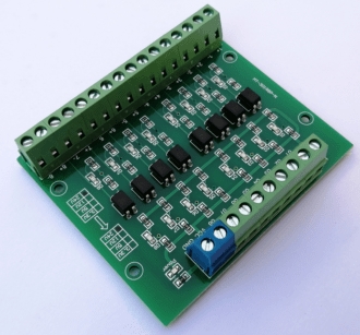
The Isolation Photo Coupler Control Panel ARD0011812 is an electronic module that allows managing 8 channels of 24V input, with 5V NPN output. It provides electrical isolation between power circuits and control circuits.
Features
- 8 channels of input
- Input voltage: 24V
- Output voltage: 5V
- Output type: NPN
What it is for
This panel is ideal for projects requiring isolation between power circuits and logic circuits, such as lighting control systems, temperature sensors or motors. Its compatibility with Arduino and other microcontrollers makes it versatile for a wide range of applications.
Tutorial: How to use the Isolated 8 Channel Control Panel
The isolated control panel 8 channels is a crucial component for projects requiring isolation between power and logic circuits. Ideal for makers working with Arduino or other microcontrollers, this module allows managing the voltage level between 24V input and 5V NPN output.
What you need
- Arduino or microcontroller
- Wired connections
- Isolated control panel 8 channels
Steps
- Connect the module’s power pins (VCC and GND) to 5V and GND of the Arduino.
- Connect the Arduino’s data pins (digital) to the module’s command pins.
- Connect the module’s input pins (24V) to sensors or the power circuit.
- Connect the module’s output pins (5V NPN) to relays or control devices.
- Check the datasheet for specific pin configuration.
- Write the Arduino sketch to manage the module’s commands.
- Test the module functionality with a simple code example.
- Verify the stability and effectiveness of the system with various input/output tests.
Example code
void setup() {
  pinMode(2, OUTPUT);
  pinMode(3, OUTPUT);
  // altri pin ...
}

void loop() {
  digitalWrite(2, HIGH);
  delay(1000);
  digitalWrite(2, LOW);
  delay(1000);
  // altri comandi ...
}
Mini project
Create a control system for a small lighting installation, where the light sensors (24V) activate the relays (5V NPN) through the isolation module 8 channels.
Common mistakes
- Do not correctly verify the polarity of the pins.
- Do not properly configure the command pins.
- Do not test the module commands before full use.
- Do not consider the need for isolation between power and logic circuits.
Recommended accessories
- 5V relay
- 24V light sensors
- Connection cables
- Arduino Uno
Frequently asked questions
Can the module handle more than 8 channels?
No, the module is designed for 8 channels only.
Can the Arduino be directly connected to the 24V sensors?
No, an isolation module must be used to protect the logic circuit.
What advantages does isolation offer?
Insulation protects the logic circuit from electrical surprises and separates voltage levels.
Reviews
There are no reviews yet.