 EN
 IT Italiano
 ES Español
 FR Français
 DE Deutsch
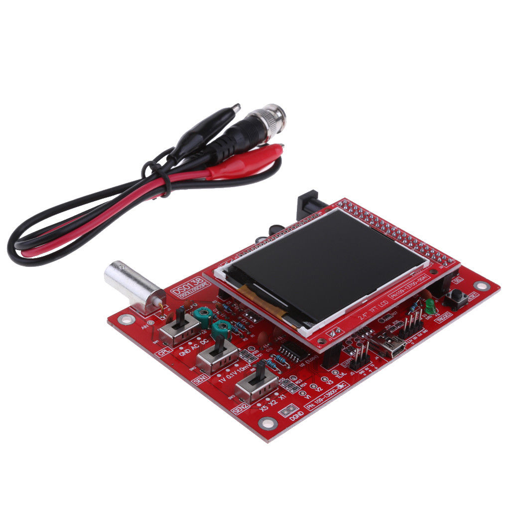
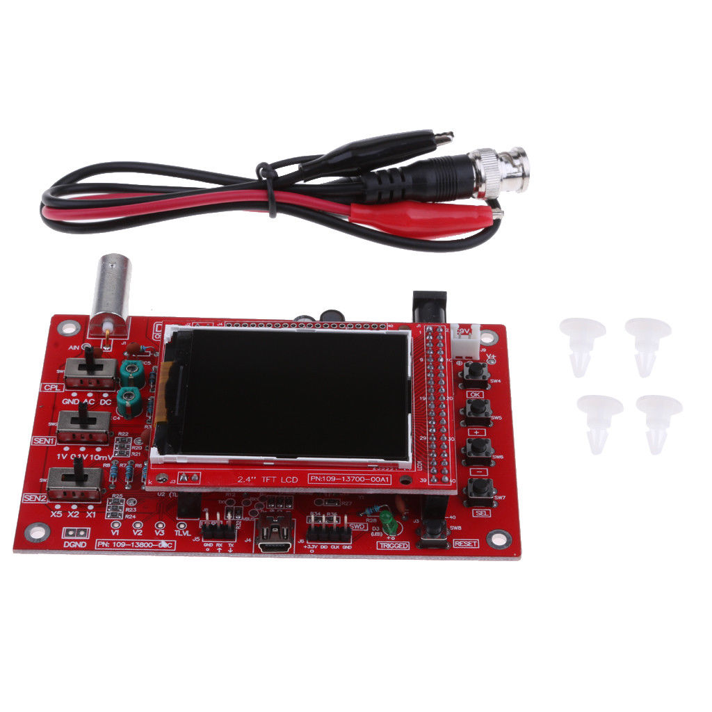
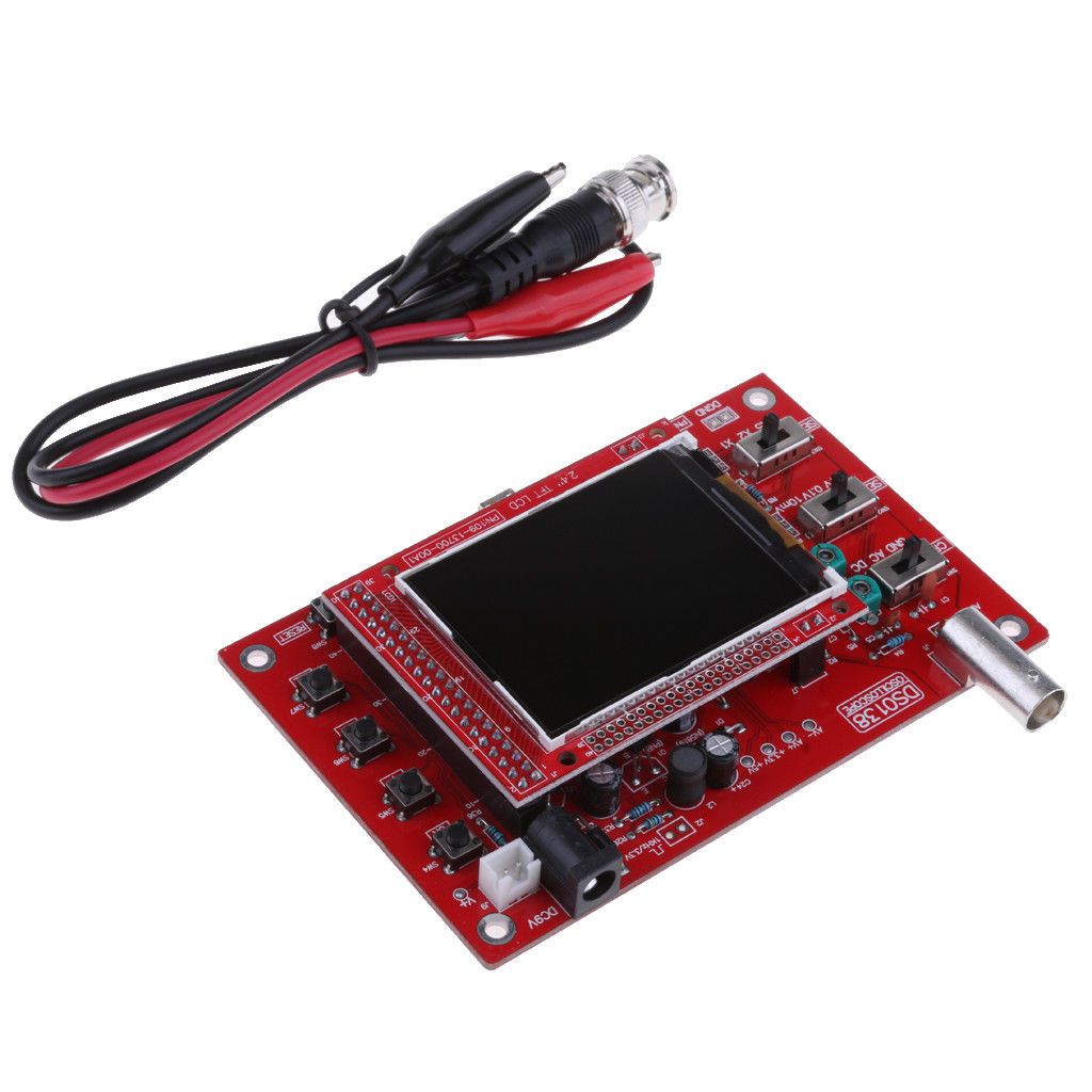
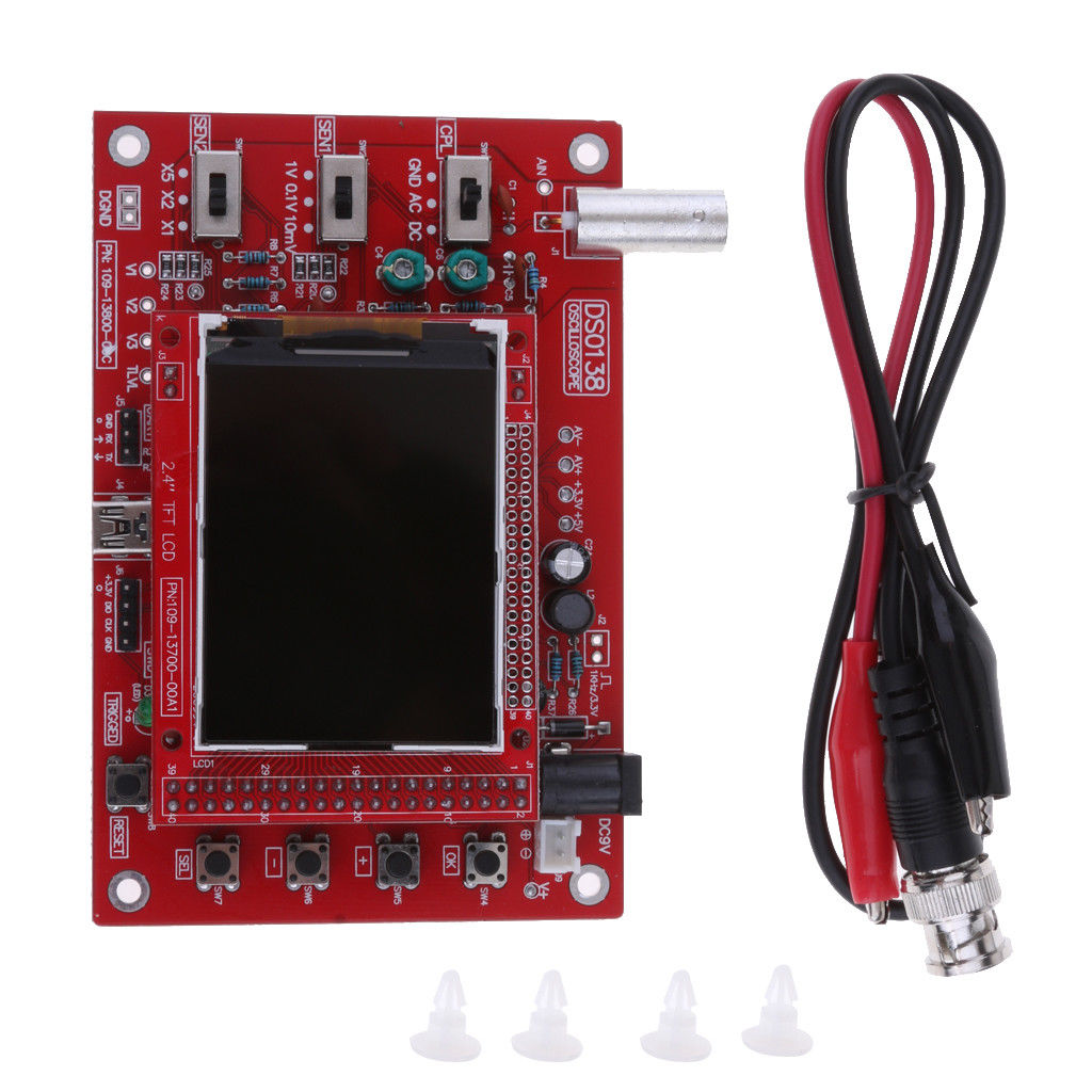
Description
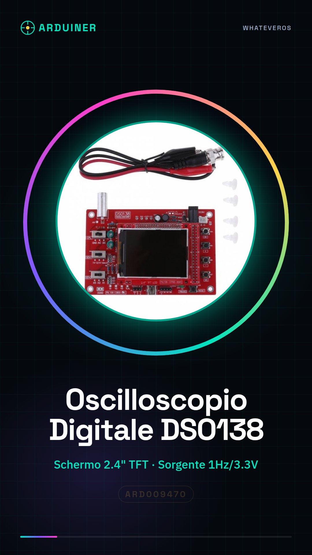
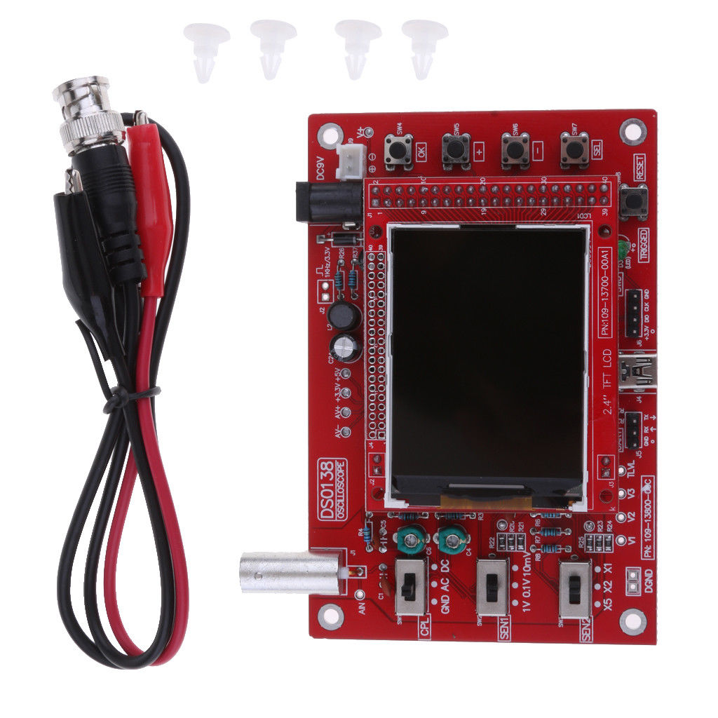
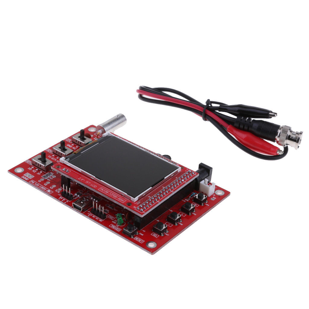
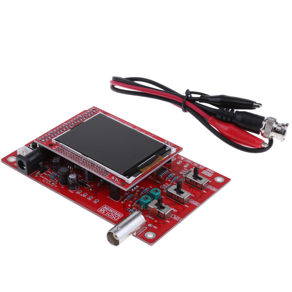
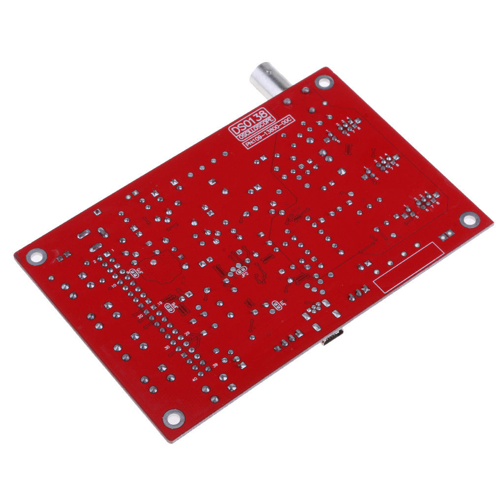
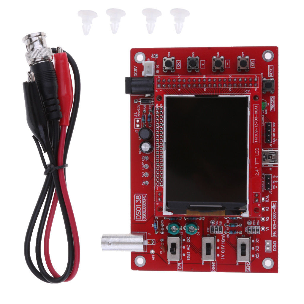
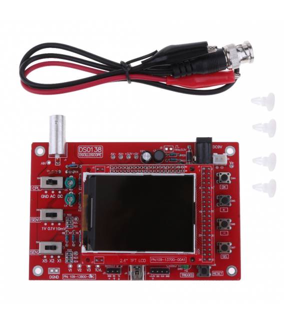
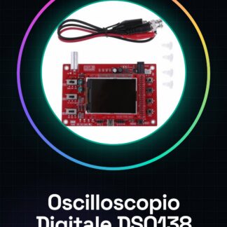
DSO138 Digital Oscilloscope Kit with 2.4 Inch TFT LCD Screen
Description:
– This DSO138 digital oscilloscope kit is easy to install and reliable for circuit operation.
– This soldered (assembled), can be used directly. can be used as a test development board ; can be a secondary development based on this kit, for example can be changed into Millivoltmeter, data logger.
– Adjustable vertical shift and with instructions.
– With automatic, adjustable and one-shot, easy to capture the momentary waveform.
– Trigger available on rising or falling edge.
– Observable pre-trigger waveform (negative delay).
– Freeze the waveform display at any time (hold function).
– Provided as a square wave test signal source at 1 Hz / 3.3 V.
– With digital display of waveform parameters, including frequency, period, pulse width, duty cycle, MAX./MIN./AVG./Peak-to-Peak/virtual values.
– Waveform memory function: not the post-waveform.
Tutorial: How to Use the DSO138 Digital Oscilloscope
The DSO138 digital oscilloscope is an essential tool for makers and electronics students who want to analyze the waveforms of electrical signals. This tutorial will guide you through the installation and configuration of the device.
What you need
- DSO138 Digital Oscilloscope
- Computer with USB Type-B connector
- Power supply cable
Steps
- Connect the DSO138 to the computer via a USB Type-B cable.
- Power the oscilloscope using the supplied power supply cable.
- Start the oscilloscope GUI software by installing the necessary drivers on your computer (check the datasheet).
- Configure the sensitivity and vertical signal offset according to your needs (check the datasheet for specific details).
- Select rising or falling edge trigger as you prefer (check the datasheet for additional configuration options).
- Adjust the frequency and signal time/division.
- Start visualizing the waveforms of your electronic circuits.
- Explore additional features such as the millivoltmeter or data logger (check the datasheet for detailed instructions).
Mini project
Create a simple data logger that records the waveforms of a time-varying signal.
Common mistakes
- Do not install the necessary drivers before use.
- Configure the sensitivity and vertical signal offset incorrectly.
- Use the USB cable as a power supply instead of the provided power cable.
Recommended accessories
- USB Type B cable
- Emergency batteries
- Arduino prototyping kit
Frequently asked questions
How can I install the necessary drivers?
Download and install the oscilloscope GUI software from the manufacturer’s website (check the datasheet).
What are the basic functions of the oscilloscope?
View waveforms, adjust sensitivity and frequency.
Can it be used as a millivoltmeter?
Yes, but check the datasheet for detailed instructions.
Reviews
There are no reviews yet.