 EN
 IT Italiano
 ES Español
 FR Français
 DE Deutsch
Description
Tutorial: How to Use a 5-Pin DIN Connector
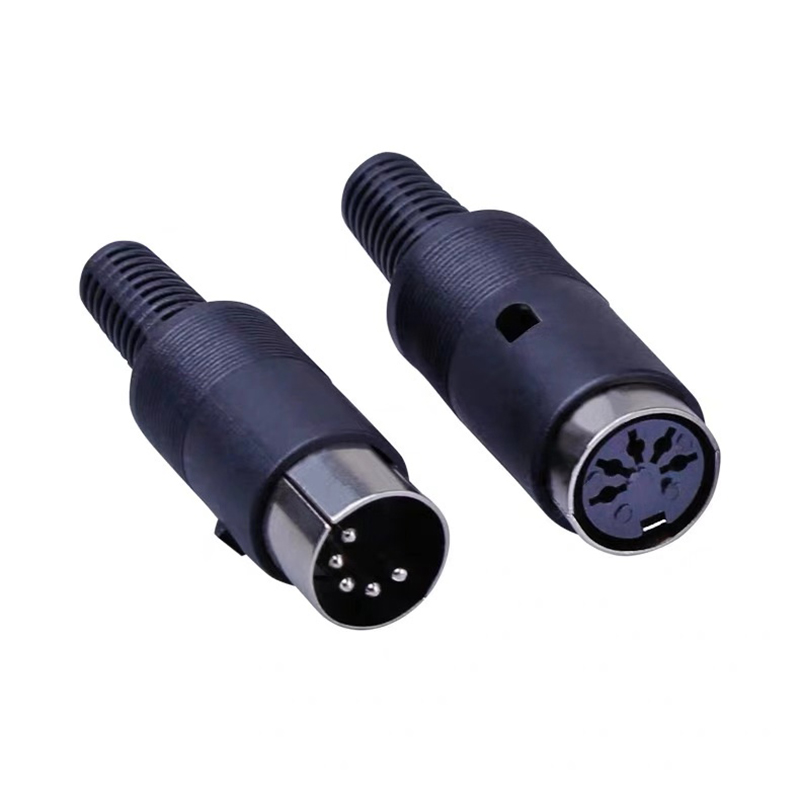
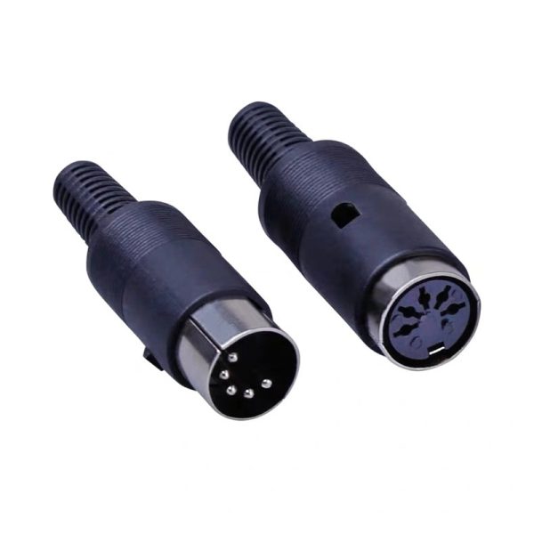
The 5-pin DIN connector is a fundamental component for electronic projects that require robust and flexible connections. This connector is ideal for connecting devices such as keyboards, mice, or for extending the functionality of an Arduino circuit.
What you need
- Arduino Projects
- Connections between computer and external devices
- 3D Printing Projects
- Control Systems
Steps
- Check the datasheet to verify the type of connector (male or female) needed for your project.
- Prepare the wires for soldering by cutting the ends and removing the insulation.
- Solder the wires to the connector, ensuring that each wire is properly soldered to a pin on the connector.
- Check the soldering to ensure there are no short circuits or weak connections.
- If necessary, apply a coating to protect the soldering.
- Connect the connector to the device or circuit.
- Check the connectivity between connected devices.
- If necessary, repeat the process for the other side of the connector (if it is a double-ended connector).
Mini project
Create a remote control system for a 3D printer using a 5-pin DIN connector to connect the motion control to the printer.
Common mistakes
- Insufficient or excessive soldering.
- Incorrect connections between the wires and the connector pins.
- Use of a connector that is not compatible with the device.
- Connectivity issues due to incorrect or damaged connections.
Recommended accessories
- Insulated wires
- Soldering kit
- Multimeter
- Electronic test kit
Frequently asked questions
How can I tell if my connector is male or female?
Check the connector datasheet or observe physically: external contacts are male and internal contacts are female.
What is the difference between a 5-pin connector and a 3-pin connector?
The number of pins determines the number of electrical connections that the connector can handle. A 5-pin connector can handle more connections than a 3-pin connector.

Reviews
There are no reviews yet.