 EN
 IT Italiano
 ES Español
 FR Français
 DE Deutsch
Description
What it is
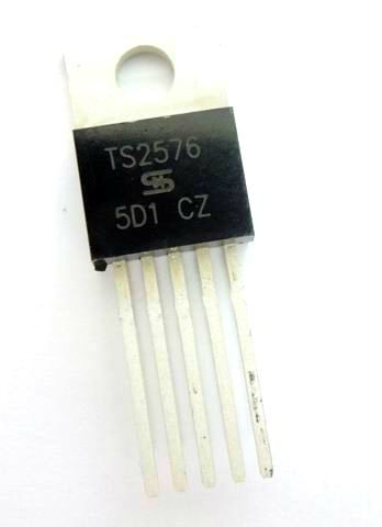
The TS2576 is a switching voltage regulator integrated circuit step-down (buck), produced by Taiwan Semiconductor. Receives a higher continuous voltage, up to 40 V, and reduces it to a lower and stable voltage, delivering up to 3 A. It is equivalent to the classic LM2576: same function, same pins.
Compared to a linear regulator like the 7805, it wastes much less energy as heat: for this reason, it is used when the difference between input and output is large (for example, from 24 V to 5 V) or when the current is high.
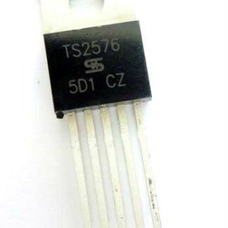
This item is the only IC in the TO-220 5-pin package (code CZ5): to make it work, a few external components are needed, listed below. It is not a ready-to-use module.
Features
- Type: switching step-down (buck) regulator
- Input voltage: up to 40 V
- Output current: up to 3 A
- Output adjustable version: from 1.23 V to 37 V
- Switching frequency: 52 kHz fixed
- Output precision: ±4% maximum
- Standby current: 70 µA typical
- Protection: current limit and thermal shutdown
- Package: TO-220 with 5 leads (5 + fin)
- Manufacturer: Taiwan Semiconductor (TSC)
Datasheet information from the manufacturer (TS2576 family). The family exists in adjustable and fixed voltage versions (3.3 V, 5 V, 12 V): the version is read from the suffix printed on the part after «CZ5». Without suffix it is the adjustable version. If you need a specific version, ask Lana before ordering.
Leads
- Lead 1: input (VIN)
- Lead 2: switching output (SW)
- Lead 3: ground (GND)
- Lead 4: feedback (Feedback)
- Lead 5: enable (Enable, to ground = on)
The order and function of the leads should always be compared with the datasheet before soldering. The metal fin is connected to ground.
What it is for
It is used to build an efficient power supply starting from a battery or a higher voltage power supply. Typical examples:
- to derive 5V for Arduino, ESP32 or Raspberry Pi from a 12V battery or a 24V system
- to power LED strips, motors and servos from a single source
- to charge or power USB devices in cars, campers or boats
- to replace a linear regulator that gets too hot
- to repair power supplies and boards that mount an LM2576 or TS2576
Who uses it and when
It is suitable for those who can read a schematic and solder: hobbyists, electronics students, repairmen. If you just want to step down a voltage without building the circuit, it is more convenient to use a pre-assembled module like the adjustable step-down converter LM2596S.
In the package
- 4 TS2576 integrated circuits in TO-220 package with 5 pins
Inductor, diode, capacitors and heat sink are not included.
Compatibility
- Replace LM2576 in the same TO-220-5 package (same pinout: check the datasheet)
- Power any board at 3.3 V or 5 V: Arduino, ESP32, ESP8266, Raspberry Pi Pico
- Not pin-to-pin compatible with surface mount LM2596 (different package)
Complete your project
- Schottky diode 1N5822 (10 pieces): the 3 A Schottky diode required by the circuit
- Electrolytic capacitor 100 µF 25 V (10 pieces): for the input, only if the input voltage stays below 20 V
- Breadboard 830 holes: for low current testing before soldering
- LM2576S-ADJ (4 pieces): the same regulator in surface mount version
- Step-down module LM2596S: the ready-to-use alternative, no soldering required
Tutorial: how to use the TS2576 to get 5 V from 12 V
Let’s build a step-down power supply with the adjustable version. The schematic is the typical one from the datasheet: an input capacitor, the integrated circuit, a Schottky diode, an inductor, and an output capacitor, plus two resistors to set the voltage.
What you need
- 1 adjustable TS2576 integrated circuit
- 1 electrolytic capacitor of at least 100 µF at the input, with a working voltage higher than the input voltage
- 1 Schottky diode of 3 A, for example 1N5822
- 1 power inductor (the typical value of the reference schematic is 100 µH, with current adequate to the load)
- 1 electrolytic output capacitor (typical value of the reference schematic: 1000 µF)
- 2 resistors for the feedback divider
- Multimeter and, above 1 A or so, a heatsink for TO-220
Steps
- Download the TS2576 datasheet and keep the ‘typical application’ schematic and pinout in front of you.
- Mount the input capacitor as close as possible to pins 1 (VIN) and 3 (GND).
- Connect the cathode of the Schottky diode to pin 2 (output) and the anode to ground, with short traces.
- Connect the inductor between pin 2 and the power supply output; place the capacitor near the output towards ground.
- Calculate the voltage divider: Vout = 1.23 × (1 + R2 / R1). With R1 = 1 kΩ, for 5 V you need R2 of about 3.1 kΩ (R2 from the output to pin 4, R1 from pin 4 to ground).
- Connect pin 5 (Enable) to ground to keep the regulator on.
- Power with 12 V without load and measure the output with the multimeter: it should be close to 5 V.
- Only then connect the load. If the IC gets hot to the touch, add a heatsink or reduce the current.
Mini project
Car adapter for Arduino: input from a 12V socket, output at 5V for the board and a strip of LEDs. By connecting the Enable pin to a switch, you can turn everything off and reduce consumption to less than 0.1 mA.
Common mistakes
- Using a normal diode (1N4007) instead of Schottky: the regulator heats up and performs poorly
- Using a small signal inductor: it saturates and the output drops under load
- Putting a capacitor with a working voltage lower than the input voltage
- Long wires between the IC, diode and input capacitor: create noise and instability
- Testing at high current on breadboard: contacts can’t handle 3A
- Connecting the load before measuring the output voltage
Recommended accessories
- TO-220 heat sink with thermal paste
- Multimeter
- Veroboard for final mounting
Frequently asked questions
What is the difference between TS2576 and LM2576?
They are the same type of regulator made by different manufacturers: 3 A, 52 kHz, same pins in the TO-220 5-pin package. Always compare the two datasheets before replacing one with the other.
And what about the LM2596?
The LM2596 operates at a higher frequency (150 kHz) and uses smaller inductors. The 2576 at 52 kHz requires a larger inductor but is very common in repairs.
Can I use it without an inductor and Schottky diode?
No. It is a switching regulator: without an inductor, Schottky diode, and capacitors, it does not work and can be damaged.
Do I need a heatsink?
It depends on current and voltage drop. At low currents it is often not needed; as you approach 3 A, it is necessary. Practical rule: if you cannot keep your finger on it after a few minutes, you need one.
How do I know if mine is adjustable or fixed voltage?
Read the printed acronym: after “CZ5” there may be a suffix with the voltage (for example 5 V). Without suffix it is the adjustable version. In doubt, write to Lana on WhatsApp at +39 345 847 1357.
Can I get a higher voltage than the input?
No, it is only step-down: the output is always lower than the input.
Reviews
There are no reviews yet.