 EN
 IT Italiano
 ES Español
 FR Français
 DE Deutsch
Description
Technical Description
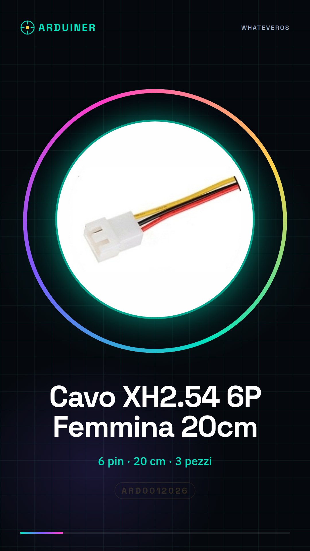
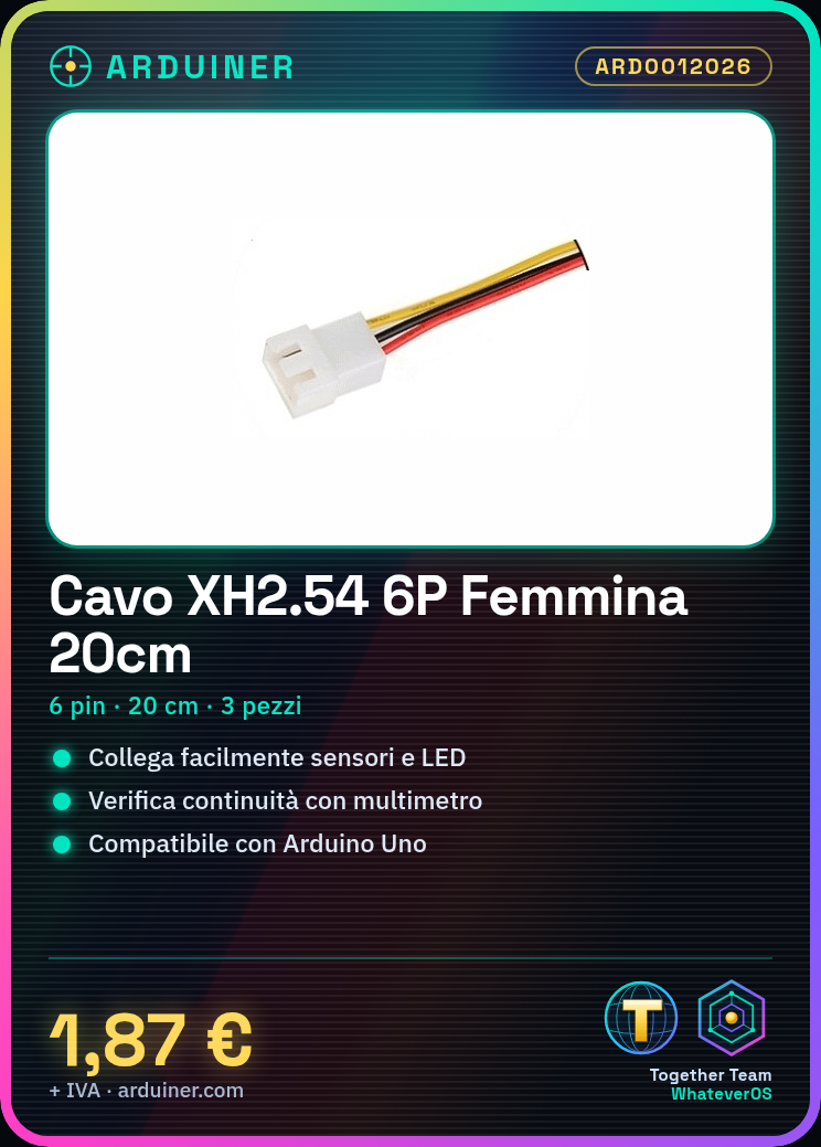
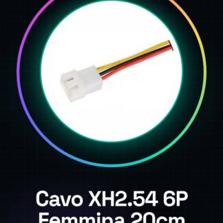
The XH2.54 6P female 20cm cable is an electronic connector used to establish stable connections between various devices and electronic components. This type of connector is particularly suitable for connecting sensors, LEDs, Arduino modules, and other components that require a flexible and robust connection.
The XH2.54 6P female cable allows for easy connection of electronic components, providing a practical solution for prototyping and realizing electronic projects. The 20cm length and the number of connection points (6) make this cable versatile for various applications.
To ensure a correct and stable connection, it is important to verify that the connector is compatible with the source and destination devices and that all lines are soldered correctly.
Key Specifications
| Parameter | Value |
| Model | XH2.54 6P Female |
| Quantity | 3 pieces |
| Length | 20cm |
| Number of connection points | 6 |
| Connector type | Female |
| Container | N/D (see manufacturer’s technical sheet) |
Installation and Usage
- Check the compatibility of the XH2.54 connector with the source and destination devices.
- Connect one end of the cable to the source device (e.g., a sensor).
- If necessary, solder the connector to the other end of the cable.
- Verify the correct installation by checking that all lines are properly soldered and there are no short circuits.
- Connect the other end of the cable to the destination device (e.g., Arduino Uno).
Compatibility and Requirements
- This cable is compatible with electronic devices that use female XH2.54 connectors.
- This cable can be used with Arduino Uno and other compatible modules and sensors.
- To use this cable, it is necessary to have a source device and a destination device with compatible connectors.
Limitations and Important Notes
- This cable is not designed for connections with connectors of other types (e.g., SMA, BNC).
- It is important to verify the compatibility of the connectors before using the cable.
- Ensure that the connections are soldered correctly to avoid short circuits.
- Use testing tools such as multimeters to check the continuity of the lines.
Troubleshooting
The cable does not work properly.
Probable cause: Incorrect soldering or wrong connections.
Solution: Check the soldering and connections with a multimeter.
The LED does not light up when the sensor is activated.
Probable cause: Wrong connections or short circuit.
Solution: Check the connections and verify the continuity of the lines.
The wire breaks easily.
Probable cause: Extreme usage conditions.
Solution: Use the wire in appropriate environments and protect the connectors.
The connector comes loose easily.
Probable cause: Incorrect soldering.
Solution: Resolder the connector correctly and check the stability of the connections.
Use cases
Home security system
Objective: Create an alarm system that turns on an LED when a motion detector is triggered.
What is needed: Arduino Uno, motion detector, LED.
Steps: 1) Check the connector compatibility. 2) Connect the detector to the wire. 3) Connect the wire to the Arduino Uno. 4) Verify the proper functioning of the system with a multimeter.
Expected result: The alarm system works correctly, turning on the LED when the detector is triggered.
Prototyping project
Objective: Connect a temperature sensor to an Arduino module.
Required: Arduino Uno, temperature sensor.
Steps: 1) Check connector compatibility. 2) Connect the sensor to the cable. 3) Connect the cable to the Arduino Uno. 4) Verify the correct functioning of the system with a multimeter.
Expected result: The temperature sensor is correctly connected to the Arduino Uno and sends temperature data.
Lighting Project
Objective: Create a lighting system controlled by a light sensor.
Required: Arduino Uno, light sensor, LED.
Steps: 1) Check connector compatibility. 2) Connect the sensor to the cable. 3) Connect the cable to the Arduino Uno. 4) Verify the correct functioning of the system with a multimeter.
Expected result: The lighting system works correctly, turning on the LED when the light sensor detects darkness.
Environmental Monitoring Project
Objective: Monitor ambient temperature and humidity.
Required: Arduino Uno, temperature and humidity sensor.
Steps: 1) Check connector compatibility. 2) Connect the sensor to the cable. 3) Connect the cable to the Arduino Uno. 4) Verify the proper functioning of the system with a multimeter.
Expected result: The monitoring system works correctly, detecting and sending temperature and humidity data.
Step Counter Project
Objective: Create a step counter to monitor physical activity.
Required: Arduino Uno, motion sensor.
Steps: 1) Check connector compatibility. 2) Connect the sensor to the cable. 3) Connect the cable to the Arduino Uno. 4) Verify the proper functioning of the system with a multimeter.
Expected result: The step counter works correctly, recording and sending motion data.
Access Control Project
Objective: Create an access control system based on a motion sensor.
What is needed: Arduino Uno, motion sensor.
Steps: 1) Check the connector compatibility. 2) Connect the sensor to the cable. 3) Connect the cable to the Arduino Uno. 4) Verify the proper functioning of the system with a multimeter.
Expected result: The access control system works correctly, detecting movements and sending access data.
Environmental Conditions Monitoring Project
Objective: Monitor environmental conditions such as temperature and humidity.
What is needed: Arduino Uno, temperature and humidity sensor.
Steps: 1) Check the connector compatibility. 2) Connect the sensor to the cable. 3) Connect the cable to the Arduino Uno. 4) Verify the proper functioning of the system with a multimeter.
Expected Outcome: The monitoring system functions correctly, detecting and sending data on environmental conditions.
Energy Control Project
Objective: To create an energy control system for electronic devices.
What’s needed: Arduino Uno, energy sensor.
Steps: 1) Check the connector compatibility. 2) Connect the sensor to the cable. 3) Connect the cable to the Arduino Uno. 4) Verify the proper functioning of the system with a multimeter.
Expected Outcome: The energy control system functions correctly, detecting and sending data on energy consumption.
In the package
- 3 pieces
Complete the project
- UFL Female to SMA Female Connector Cable 20CM for Antennas: This cable is often used with motion sensors for home alarm projects.
Technical FAQs
How can I verify that the connector is soldered correctly?
Use a multimeter to check the continuity between the connector pins and those of the underlying circuit.
What is the importance of using this type of cable instead of others?
These cables are specifically designed to withstand extreme conditions and provide a stable connection between components.
What tools are needed to solder the connector?
It is necessary to use a soldering iron and an appropriate soldering kit.
What is the recommended maximum length for this type of cable?
The recommended maximum length for this type of cable is 20cm to ensure a stable and reliable connection.
Tutorial: How to use XH2.54 6P Female 20CM Cable
The XH2.54 cable is a connector used to connect various electronic devices such as sensors, LEDs, or other Arduino modules. This tutorial will guide you through the use of this cable in basic projects.
What you need
- Arduino Uno
- Sensors
- LED
Steps
- Check that the XH2.54 connector is compatible with your electronic devices.
- Connect one end of the cable to your source device (e.g., a sensor).
- Use the necessary tools to solder the connector to the other end if it is not already done.
- Verify the correct installation by checking that all lines are well soldered and without short circuits.
- Connect the other end of the cable to the destination device (e.g., Arduino Uno).
- Check the connections with a multimeter to ensure there are no interruptions or short circuits.
- If necessary, use the Arduino IDE software to write and upload a test sketch.
- Verify the proper functioning of the cable by performing tests on your project.
Mini project
Create a simple alarm system with a motion sensor connected to Arduino. The alarm should turn on an LED when the sensor is activated.
Common mistakes
- Incorrect soldering
- Damaged connectors
- Incorrect connections
Recommended accessories
- Arduino Uno
- Motion sensors
- LED
Frequently asked questions
How can I verify that the connector is soldered correctly?
Use a multimeter to check continuity between the connector pins and those of the underlying circuit.
What is the importance of using this type of cable instead of others?
These cables are specifically designed to withstand extreme conditions and provide a stable connection between components.
Reviews
There are no reviews yet.