 EN
 IT Italiano
 ES Español
 FR Français
 DE Deutsch
Description
What it is
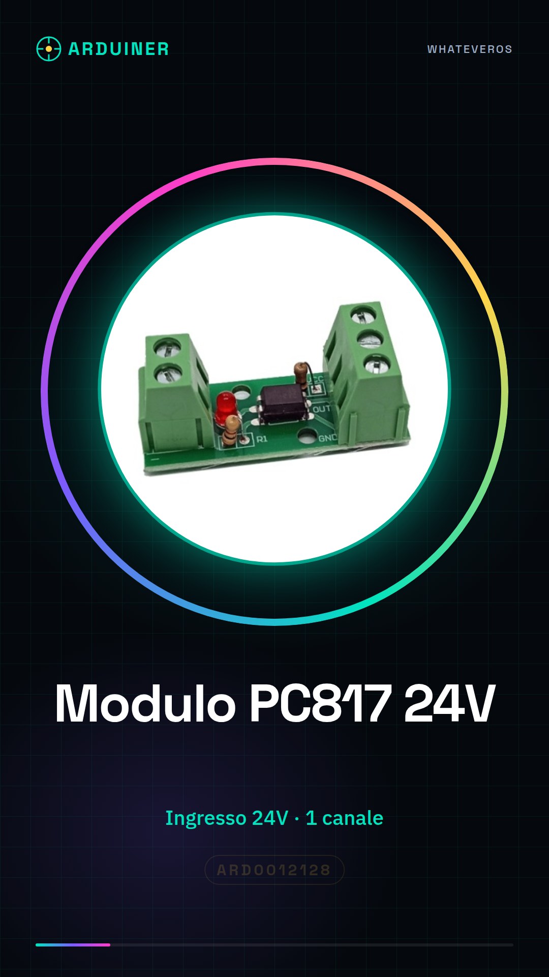
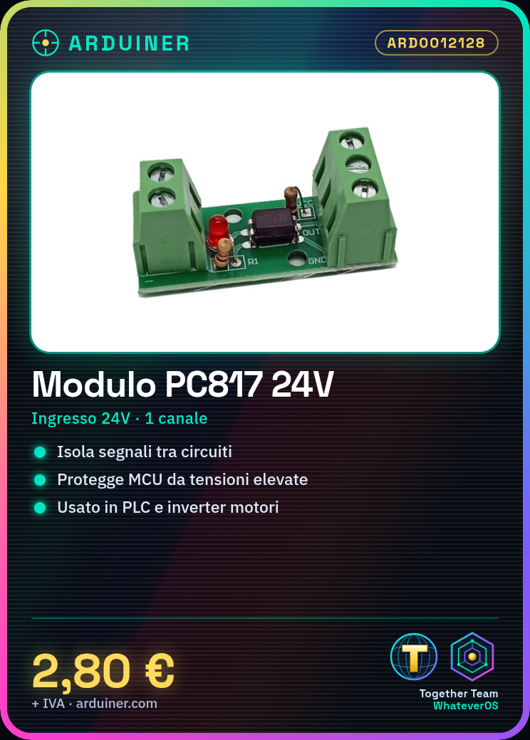
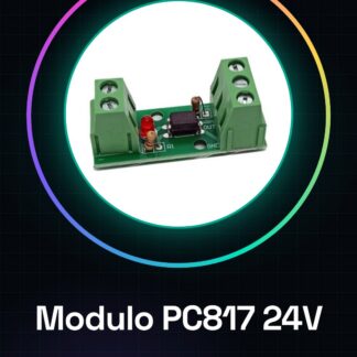
The PC817 EL817 optocoupler module is an electronic device that allows two electrical circuits to be isolated. This means that electrical signals can pass from the input circuit to the output circuit without a direct physical connection.
Features
- 24V Input
- PC817 EL817 Optocoupler Output
- 1 Channel
- Optocoupler Isolation Module
What it is for
This module is ideal for isolating signals between two parts of a circuit, protecting and ensuring the safety of your electronic system. It is particularly useful in applications with high current circuits or with potential differences in potential. It can be used with PLCs, motor inverters, and other electronic devices.
Tutorial: How to use the PC817 Optocoupler Isolation Module
This module is ideal for isolating signals between two parts of a circuit, protecting and ensuring the safety of your electronic system. Useful for beginners and intermediates in electronics.
What you need
- Arduino or microcontroller
- 24V Power Supply
- 1kΩ Resistor
- Connection Wire
Steps
- 1. Check the datasheet for power supply and output voltage specifications.
- 2. Connect the 24V power supply to the VCC pin of the PC817.
- 3. Connect the GND pin of the PC817 to the GND of your circuit.
- 4. Connect the input signal to the IN pin of the PC817.
- 5. Connect the OUT pin of the PC817 to your microcontroller.
- 6. Set a 1kΩ resistor between the OUT pin and GND to protect the microcontroller.
- 7. Load a simple Arduino sketch to test the module.
- 8. Verify that the output signal is correctly isolated and transferred.
Example code
```cpp
int inputPin = 2;
int outputPin = 3;

void setup() {
  pinMode(outputPin, OUTPUT);
}

void loop() {
  digitalWrite(outputPin, digitalRead(inputPin));
}
```
Mini project
Create a simple light switch using a 24V electric button and an LED. Use the PC817 to protect the microcontroller.
Common mistakes
- Do not check the specifications on the datasheet.
- Connect the output signal directly to the microcontroller without a resistor.
- Use a voltage source different from 24V.
- Omit the verification of the output signal.
Recommended accessories
- Arduino Uno
- LED
- 24V Switch
- 1kΩ Resistor
Frequently asked questions
How can I verify that the module works correctly?
Measure the output voltage with a multimeter and verify that it is isolated from the input voltage.
Can I use this module with voltages different from 24V?
Check the datasheet to see if the module supports different voltages.
Can the PC817 module be used in AC circuits?
The PC817 is designed for DC circuits, check if it supports AC.
Reviews
There are no reviews yet.