 EN
 IT Italiano
 ES Español
 FR Français
 DE Deutsch
Description
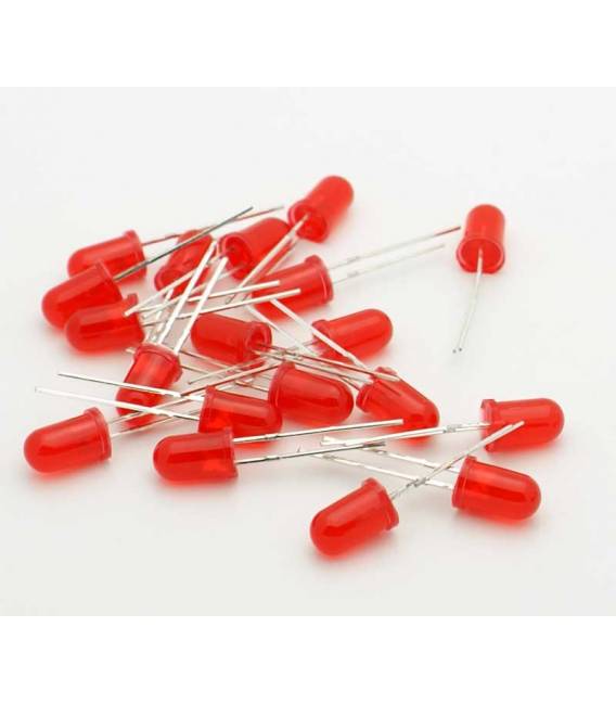
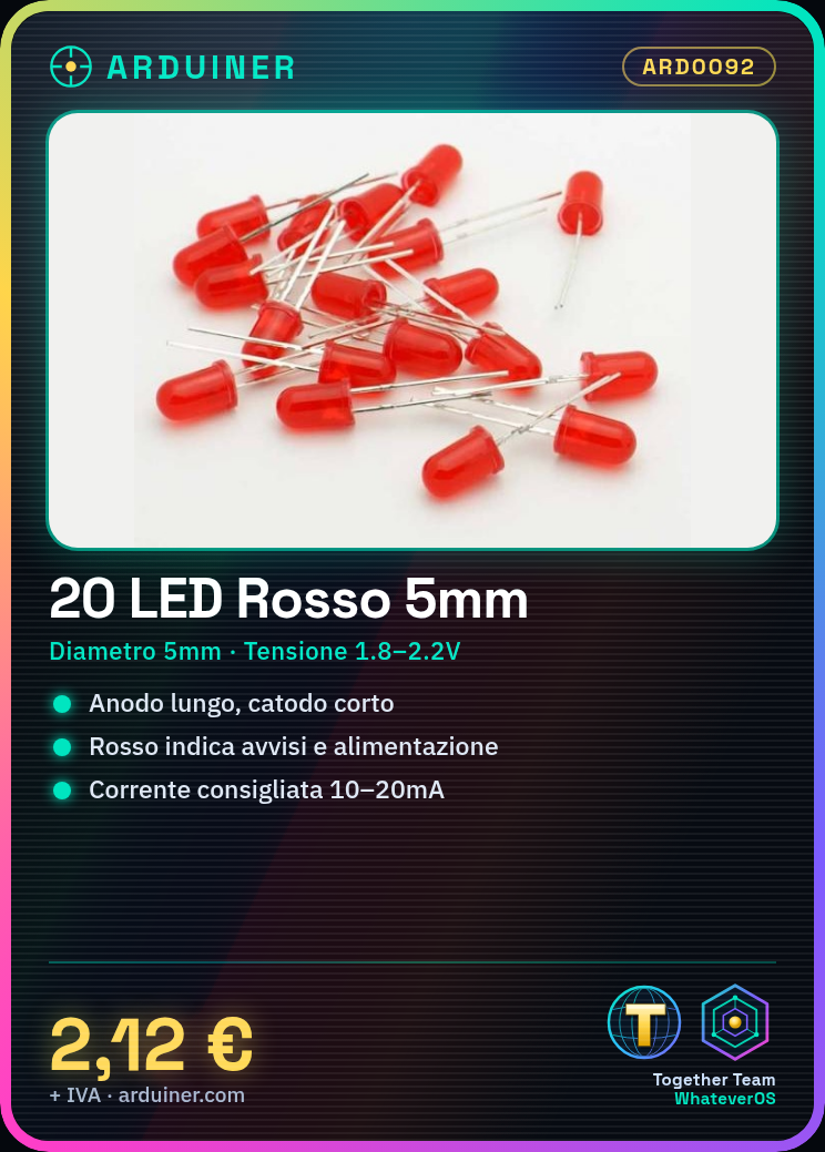
🔌 Description of LEDs (5 mm LED Diode)
📏 General Characteristics
- Type: LED Diode (Light Emitting Diode)
- Diameter: 5 mm
- Typical Operating Voltage:
- Red: 1.8–2.2 V
- Yellow: 2.0–2.2 V
- Green: 2.0–3.2 V
- Blue: 3.0–3.4 V
- White: 3.0–3.4 V
- Recommended Current: 10–20 mA
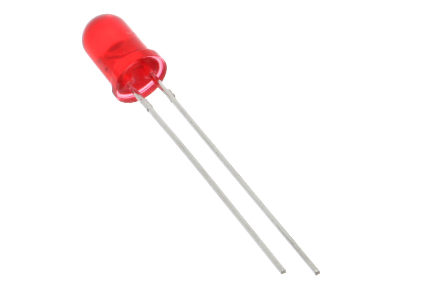
- Polarity: Anode (positive, longer leg) and Cathode (negative, shorter leg)
🎨 Available Colors
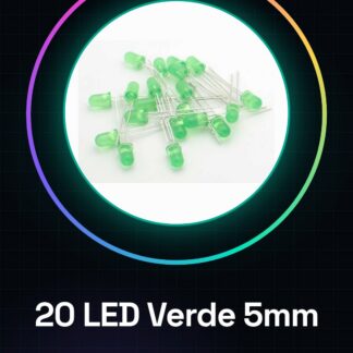
- Green LED: Used to indicate active or OK status.
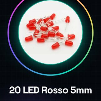
- Red LED: Symbolizes warnings, errors, or power.
- White LED: For illumination or neutral signaling.
- Yellow LED: Attention or standby status.
- Blue LED: Modern, often used for power-on or special status.
🛠️ Guide for use with Arduino
🔧 Required components
- Arduino UNO (or compatible)
- Resistors of 220Ω or 330Ω
- 5 mm LEDs (color of choice)
- Breadboard
- Jumper wires
📈 Connection diagram (single LED)
Arduino PIN (es. 13) ---> Resistenza (220Ω) ---> Anodo LED
                                      |
                                  Catodo ---> GND
- Connect the long leg of the LED (anode) through a 220Ω resistor to an Arduino digital pin.
- Connect the short leg (cathode) to the GND of Arduino.
💻 Example code: turn on an LED
// Pin a cui è collegato il LED
int ledPin = 13;

void setup() {
  pinMode(ledPin, OUTPUT); // imposta il pin come uscita
}

void loop() {
  digitalWrite(ledPin, HIGH); // accende il LED
  delay(1000);                // attende 1 secondo
  digitalWrite(ledPin, LOW);  // spegne il LED
  delay(1000);                // attende 1 secondo
}
🧪 Example: turn on 5 LEDs of different colors
⚙️ Connection
| LED | Arduino PIN | Resistor |
|---|---|---|
| Red | 2 | 220Ω |
| Green | 3 | 220Ω |
| Yellow | 4 | 220Ω |
| Blue | 5 | 330Ω |
| White | 6 | 330Ω |
🔤 Arduino Code for LED Sequence
int ledRosso = 2;
int ledVerde = 3;
int ledGiallo = 4;
int ledBlu = 5;
int ledBianco = 6;

void setup() {
  pinMode(ledRosso, OUTPUT);
  pinMode(ledVerde, OUTPUT);
  pinMode(ledGiallo, OUTPUT);
  pinMode(ledBlu, OUTPUT);
  pinMode(ledBianco, OUTPUT);
}

void loop() {
  digitalWrite(ledRosso, HIGH);
  delay(500);
  digitalWrite(ledRosso, LOW);

  digitalWrite(ledVerde, HIGH);
  delay(500);
  digitalWrite(ledVerde, LOW);

  digitalWrite(ledGiallo, HIGH);
  delay(500);
  digitalWrite(ledGiallo, LOW);

  digitalWrite(ledBlu, HIGH);
  delay(500);
  digitalWrite(ledBlu, LOW);

  digitalWrite(ledBianco, HIGH);
  delay(500);
  digitalWrite(ledBianco, LOW);
}
📘 Practical Tips
- Use different resistors for each color to avoid damage: blue and white require higher values.
- If you want more control, consider using transistors o LED drivers for higher current.
- You can combine these LEDs to create a traffic light, a status indicator, or simple lighting effects.
🧠 Advanced Experiments
- PWM (Pulse Width Modulation): Use
analogWrite(pin, valore)to adjust brightness. - Sensors: Turn on LEDs in response to light, temperature, or motion sensors.
- Light effects: Create breathing, random flashing, or music-synced effects.
Perfect! Here are 3 advanced examples of using 5mm LEDs with Arduino:
🚦 1. Traffic Light with LEDs
🔧 Components
- 1 Red LED (Pin 2)
- 1 Yellow LED (Pin 3)
- 1 Green LED (Pin 4)
- 3 Resistors (220Ω)
- Arduino, breadboard, jumper
💡 Schematic
Connect the LEDs through resistors to pins 2, 3, 4 respectively and GND.
🧠 Code
int ledRosso = 2;
int ledGiallo = 3;
int ledVerde = 4;

void setup() {
  pinMode(ledRosso, OUTPUT);
  pinMode(ledGiallo, OUTPUT);
  pinMode(ledVerde, OUTPUT);
}

void loop() {
  digitalWrite(ledRosso, HIGH);
  delay(3000); // 3 secondi
  digitalWrite(ledRosso, LOW);

  digitalWrite(ledGiallo, HIGH);
  delay(1000); // 1 secondo
  digitalWrite(ledGiallo, LOW);

  digitalWrite(ledVerde, HIGH);
  delay(3000); // 3 secondi
  digitalWrite(ledVerde, LOW);
}
🔘 2. LED Toggle with Button (on/off)
🔧 Components
- 1 LED (e.g. Blue, Pin 8)
- 1 LED Resistor (330Ω)
- 1 Button (Pin 7)
- 1 Pull-down Resistor (10kΩ)
- Arduino
🔌 Connection
- LED (Anode to Pin 8 through resistor, Cathode to GND)
- Button between Pin 7 and 5V, with pull-down between Pin 7 and GND
🧠 Code
int ledPin = 8;
int buttonPin = 7;
bool statoLED = false;
bool statoPrecedente = false;

void setup() {
  pinMode(ledPin, OUTPUT);
  pinMode(buttonPin, INPUT);
}

void loop() {
  bool lettura = digitalRead(buttonPin);
  if (lettura == HIGH && statoPrecedente == LOW) {
    statoLED = !statoLED;
    digitalWrite(ledPin, statoLED);
    delay(200); // debounce
  }
  statoPrecedente = lettura;
}
📱 3. LED Control via Bluetooth (from App)
🔧 Components
- LED (Red – Pin 10)
- HC-05 Bluetooth module (TX/RX)
- Arduino UNO
📲 Recommended App: Serial Bluetooth Terminal (Android) or similar
🧠 Connection
- Red LED at Pin 10 (through 220Ω resistor)
- HC-05:
- TX ➝ RX (Pin 0 of Arduino)
- RX ➝ TX (Pin 1 of Arduino, with voltage divider resistor)
- VCC ➝ 5V
- GND ➝ GND
🔥 Note: disconnect TX/RX when uploading sketch to Arduino.
🧠 Code
int ledPin = 10;
char comando;

void setup() {
  pinMode(ledPin, OUTPUT);
  Serial.begin(9600);
}

void loop() {
  if (Serial.available()) {
    comando = Serial.read();
    if (comando == '1') {
      digitalWrite(ledPin, HIGH);
    } else if (comando == '0') {
      digitalWrite(ledPin, LOW);
    }
  }
}
📲 Commands from app
- Send 1 ➝ LED on
- Send 0 ➝ LED off
Perfect! The effect “breathing” (also known as fading LED) simulates the behavior of a light that slowly turns on and off, just like it’s “breathing”. It’s a great exercise to learn the PWM (Pulse Width Modulation) with Arduino.
🌬️ Project: LED with breathing effect (fading)
🔧 Required Components
- 1 LED (preferably White, Blue or Green for a nice visual effect)
- 1 Resistor 220–330Ω
- Arduino UNO
- Breadboard and jumpers
🔌 Connection Diagram
| Component | Connection |
|---|---|
| LED Anode | Pin 9 (PWM) |
| LED Cathode | GND (via resistenza 220Ω) |
The Pin 9 of Arduino supports PWM (you can see it with the symbol
~).
💻 Arduino Code: breathing effect
int ledPin = 9;       // Pin PWM
int luminosita = 0;   // Valore PWM (0-255)
int variazione = 5;   // Incremento/decremento luminosità

void setup() {
  pinMode(ledPin, OUTPUT);
}

void loop() {
  analogWrite(ledPin, luminosita); // imposta la luminosità

  luminosita += variazione;        // cambia luminosità

  // Inverti direzione al raggiungimento di estremi
  if (luminosita <= 0 || luminosita >= 255) {
    variazione = -variazione;
  }

  delay(30); // tempo tra i cambi (più alto = respiro più lento)
}
🧪 Additional experiments
- Modify
delay(30)to make the breathing slower or faster. - Change
variazionea1for an even softer effect. - Try with a RGB LED to fade through multiple colors (want an RGB example? I can give you one!)
🎨 Variant: “sinusoidal breathing” (more natural)
For a more realistic effect, the sine function can be used to model the brightness (requires the library math.h on some Arduino versions):
int ledPin = 9;
float x = 0;

void setup() {
  pinMode(ledPin, OUTPUT);
}

void loop() {
  float valore = (sin(x) + 1.0) * 127.5; // da 0 a 255
  analogWrite(ledPin, int(valore));
  x += 0.05;
  if (x > TWO_PI) x = 0;
  delay(20);
}
This creates an even softer breathing effect, similar to that of Apple devices or smart devices.
🔌 LED Description (5 mm LED Diode)
📏 General Characteristics
- Type: LED (Light Emitting Diode)
- Diameter: 5 mm
- Typical Operating Voltage:
- Red: 1.8–2.2 V
- Yellow: 2.0–2.2 V
- Green: 2.0–3.2 V
- Blue: 3.0–3.4 V
- White: 3.0–3.4 V
- Recommended Current: 10–20 mA
- Polarity: Anode (positive, longer leg) and Cathode (negative, shorter leg)
🎨 Available Colors
- Green LED: Used to indicate active or OK status.
- Red LED: Represents warnings, errors, or power.
- White LED: For illumination or neutral signaling.
- Yellow LED: Attention or standby state.
- Blue LED: Modern, often used for power-on or special state.
🛠️ Guide to use with Arduino
🔧 Required components
- Arduino UNO (or compatible)
- Resistors of 220Ω or 330Ω
- LEDs of 5 mm (color of choice)
- Breadboard
- Jumper wires
📈 Connection diagram (single LED)
Arduino PIN (es. 13) ---> Resistenza (220Ω) ---> Anodo LED
                                      |
                                  Catodo ---> GND
- Connect the long leg of the LED (anode) using a 220Ω resistor to an Arduino digital pin.
- Connect the short leg (cathode) to the GND of Arduino.
💻 Example code: turn on an LED
// Pin a cui è collegato il LED
int ledPin = 13;

void setup() {
  pinMode(ledPin, OUTPUT); // imposta il pin come uscita
}

void loop() {
  digitalWrite(ledPin, HIGH); // accende il LED
  delay(1000);                // attende 1 secondo
  digitalWrite(ledPin, LOW);  // spegne il LED
  delay(1000);                // attende 1 secondo
}
🧪 Example: turn on 5 LEDs of different colors
⚙️ Connection
| LED | Arduino PIN | Resistor |
|---|---|---|
| Red | 2 | 220Ω |
| Green | 3 | 220Ω |
| Yellow | 4 | 220Ω |
| Blue | 5 | 330Ω |
| White | 6 | 330Ω |
🔤 Arduino Code for LED Sequence
int ledRosso = 2;
int ledVerde = 3;
int ledGiallo = 4;
int ledBlu = 5;
int ledBianco = 6;

void setup() {
  pinMode(ledRosso, OUTPUT);
  pinMode(ledVerde, OUTPUT);
  pinMode(ledGiallo, OUTPUT);
  pinMode(ledBlu, OUTPUT);
  pinMode(ledBianco, OUTPUT);
}

void loop() {
  digitalWrite(ledRosso, HIGH);
  delay(500);
  digitalWrite(ledRosso, LOW);

  digitalWrite(ledVerde, HIGH);
  delay(500);
  digitalWrite(ledVerde, LOW);

  digitalWrite(ledGiallo, HIGH);
  delay(500);
  digitalWrite(ledGiallo, LOW);

  digitalWrite(ledBlu, HIGH);
  delay(500);
  digitalWrite(ledBlu, LOW);

  digitalWrite(ledBianco, HIGH);
  delay(500);
  digitalWrite(ledBianco, LOW);
}
📘 Practical Tips
- Use different resistors for each color to avoid damage: blue and white require higher values.
- For more control, consider using transistors o LED drivers for higher current.
- You can combine these LEDs to create a traffic light, a status indicator, or simple lighting effects.
🧠 Advanced Experiments
- PWM (Pulse Width Modulation): Use
analogWrite(pin, valore)to adjust the brightness. - Sensors: Turn on LEDs in response to light, temperature, or motion sensors.
- Light effects: Create “breathing”, random flashing, or music-synced effects.
Perfect! Here are 3 advanced examples of using 5mm LEDs with Arduino:
🚦 1. Traffic light with LEDs
🔧 Components
- 1 Red LED (Pin 2)
- 1 Yellow LED (Pin 3)
- 1 Green LED (Pin 4)
- 3 Resistors (220Ω)
- Arduino, breadboard, jumper
💡 Diagram
Connect the LEDs through resistors to pins 2, 3, 4 respectively and GND.
🧠 Code
int ledRosso = 2;
int ledGiallo = 3;
int ledVerde = 4;

void setup() {
  pinMode(ledRosso, OUTPUT);
  pinMode(ledGiallo, OUTPUT);
  pinMode(ledVerde, OUTPUT);
}

void loop() {
  digitalWrite(ledRosso, HIGH);
  delay(3000); // 3 secondi
  digitalWrite(ledRosso, LOW);

  digitalWrite(ledGiallo, HIGH);
  delay(1000); // 1 secondo
  digitalWrite(ledGiallo, LOW);

  digitalWrite(ledVerde, HIGH);
  delay(3000); // 3 secondi
  digitalWrite(ledVerde, LOW);
}
🔘 2. LED Toggle with Button (on/off)
🔧 Components
- 1 LED (e.g. Blue, Pin 8)
- 1 LED Resistor (330Ω)
- 1 Button (Pin 7)
- 1 Pull-down Resistor (10kΩ)
- Arduino
🔌 Connection
- LED (Anode to Pin 8 through resistor, Cathode to GND)
- Button between Pin 7 and 5V, with pull-down between Pin 7 and GND
🧠 Code
int ledPin = 8;
int buttonPin = 7;
bool statoLED = false;
bool statoPrecedente = false;

void setup() {
  pinMode(ledPin, OUTPUT);
  pinMode(buttonPin, INPUT);
}

void loop() {
  bool lettura = digitalRead(buttonPin);
  if (lettura == HIGH && statoPrecedente == LOW) {
    statoLED = !statoLED;
    digitalWrite(ledPin, statoLED);
    delay(200); // debounce
  }
  statoPrecedente = lettura;
}
📱 3. LED Control via Bluetooth (from App)
🔧 Components
- LED (Red – Pin 10)
- HC-05 Bluetooth module (TX/RX)
- Arduino UNO
📲 Recommended App: Serial Bluetooth Terminal (Android) or similar
🧠 Connection
- Red LED on Pin 10 (through 220Ω resistor)
- HC-05:
- TX ➝ RX (Pin 0 of Arduino)
- RX ➝ TX (Pin 1 of Arduino, with voltage divider resistor)
- VCC ➝ 5V
- GND ➝ GND
🔥 Note: disconnect TX/RX when uploading sketch to Arduino.
🧠 Code
int ledPin = 10;
char comando;

void setup() {
  pinMode(ledPin, OUTPUT);
  Serial.begin(9600);
}

void loop() {
  if (Serial.available()) {
    comando = Serial.read();
    if (comando == '1') {
      digitalWrite(ledPin, HIGH);
    } else if (comando == '0') {
      digitalWrite(ledPin, LOW);
    }
  }
}
📲 Commands from app
- Send 1 ➝ LED on
- Send 0 ➝ LED off
Perfect! The effect “breathing” (also known as fading LED) simulates the behavior of a light that slowly turns on and off, just like if it were “breathing”. It’s a great exercise to learn the PWM (Pulse Width Modulation) with Arduino.
🌬️ Project: LED with breathing effect (fading)
🔧 Required components
- 1 LED (preferably White, Blue or Green for a nice visual effect)
- 1 Resistor 220–330Ω
- Arduino UNO
- Breadboard and jumpers
🔌 Connection diagram
| Component | Connection |
|---|---|
| LED anode | Pin 9 (PWM) |
| LED Cathode | GND (via resistenza 220Ω) |
Il Pin 9 di Arduino supporta PWM (lo vedi con il simbolo)
~).
💻 Codice Arduino: effetto respiro
int ledPin = 9;       // Pin PWM
int luminosita = 0;   // Valore PWM (0-255)
int variazione = 5;   // Incremento/decremento luminosità

void setup() {
  pinMode(ledPin, OUTPUT);
}

void loop() {
  analogWrite(ledPin, luminosita); // imposta la luminosità

  luminosita += variazione;        // cambia luminosità

  // Inverti direzione al raggiungimento di estremi
  if (luminosita <= 0 || luminosita >= 255) {
    variazione = -variazione;
  }

  delay(30); // tempo tra i cambi (più alto = respiro più lento)
}
🧪 Esperimenti aggiuntivi
- Modifica
delay(30)per rendere la respirazione più lenta o più veloce. - Cambia
variazionea1per un effetto ancora più morbido. - Prova con un LED RGB per fare fading su più colori (vuoi un esempio RGB? Posso dartelo!).
🎨 Variante: “respiro sinusoidale” (più naturale)
Per un effetto più realistico, si può usare la funzione seno per modellare la luminosità (richiede la libreria math.h su alcune versioni Arduino):
int ledPin = 9;
float x = 0;

void setup() {
  pinMode(ledPin, OUTPUT);
}

void loop() {
  float valore = (sin(x) + 1.0) * 127.5; // da 0 a 255
  analogWrite(ledPin, int(valore));
  x += 0.05;
  if (x > TWO_PI) x = 0;
  delay(20);
}
Questo crea un effetto “respiro” ancora più morbido, simile a quello dei dispositivi Apple o dispositivi smart.
Tutorial: How to Use 5mm Super Bright Red LEDs
Questi LED rossi super luminosi sono ideali per chiunque voglia illuminare i propri progetti elettronici in modo visibile. Sono perfetti sia per principianti che per maker più esperti.
What you need
- Arduino Uno
- jumper wire
- resistor (check the datasheet)
- breadboard
Steps
- Connect the anode (+) of the LED to the breadboard.
- Insert a resistor between the Arduino pin and the cathode (-) of the LED to protect the circuit (check the datasheet).
- Connect the cathode (-) of the LED to the common ground of the breadboard.
- Write an Arduino sketch that turns on the LED with a button connected to an input pin.
- Test the configuration by pressing the button to turn the LED on and off.
- If necessary, adjust the resistor to optimize the brightness of the LED without damaging it.
Example code
const int ledPin = 13; // pin di output
const int buttonPin = 2; // pin di input
int buttonState;
void setup() {
pinMode(ledPin, OUTPUT);
pinMode(buttonPin, INPUT_PULLUP);}
void loop() {
buttonState = digitalRead(buttonPin);
digitalWrite(ledPin, buttonState);}
Mini project
Create a simple light-up clock that turns the LED on and off every minute.
Common mistakes
- Using a resistor that is too low or no resistor at all
- Connecting the anode to the cathode of the LED
- Not checking the operating voltage on the datasheet
Recommended accessories
- Variable resistors
- Push buttons
- Arduino Uno R3
- Basic Kit for Arduino Projects
Frequently asked questions
How much current flows through the LED?
Check the specification in the datasheet.
Can I connect multiple LEDs in series?
No, you should connect them in parallel with appropriate resistors for each one.
Reviews
There are no reviews yet.