 EN
 IT Italiano
 ES Español
 FR Français
 DE Deutsch
Description
Technical Specifications
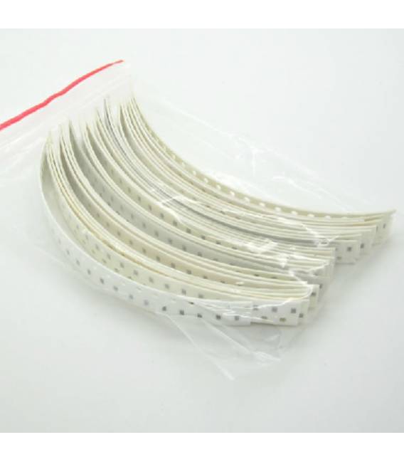
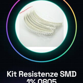
The SMD 1% 0805 resistor kit includes a variety of resistance values in surface mount (SMD) format, suitable for electronic projects that require precision and compact size. These resistors are ideal for applications that demand high accuracy and are available in a range of values covering a wide range of project requirements.
Each resistor in the kit is marked with standard SMD color codes to facilitate identification of the value. The SMD 0805 resistor is one of the most common sizes for this type of component, offering a balance between reduced size and ease of use.
This kit is particularly useful for projects that require a series of resistors with specific values, allowing the avoidance of the need to purchase each necessary component individually.
Key Specifications
| Parameter | Value |
| Model | SMD 1% 0805 Resistor Kit |
| Quantity | 50 pieces |
| Values | 0R-3.6K |
| Dimensions | 0805 |
| Precision | 1% |
| Container | Pack of 50 pieces |
Installation and Usage
- Check the values of the SMD resistors in the kit to ensure you have the ones needed for your project.
- Prepare your workstation with electronic tools such as soldering tweezers, electronic microscope (if available) and test board.
- Select an SMD resistor from the kit based on the requirements of your circuit diagram and verify the value from the datasheet if necessary.
- Position the SMD resistor on your board or PCB, ensuring it is oriented correctly according to the SMD color codes (check the datasheet).
- Solder the legs of the SMD resistor to the PCB. Use soldering tweezers and a microscope to ensure a clean solder joint.
Compatibility and Requirements
- This SMD 1% 0805 resistor kit is compatible with a wide range of boards and PCBs.
- It is suitable for projects requiring SMD resistors with 1% precision.
- A multimeter or continuity tester is needed to check soldering and component functionality.
Limitations and Important Notes
- This kit does not include resistors with values above 3.6K.
- An electronic microscope is required for soldering SMD components.
- Ensure you use a continuity tester to check soldering and component functionality.
- It is not recommended to use this kit for projects requiring resistors with precision below 1%.
Troubleshooting
The SMD resistor is not recognized by the multimeter.
Probable cause: The soldering is poor or incomplete.
Solution: Re-solder, ensuring a clean and solid solder joint.
The value of the SMD resistance does not match the expected one.
Probable cause: The color code identification is incorrect.
Solution: Verify the color code of the SMD resistance on the manufacturer’s datasheet.
The SMD resistance overheats during operation.
Probable cause: The resistance is not adequately dissipated.
Solution: Verify that the resistance is adequately dissipated and that the PCB has good heat dissipation.
The SMD resistance detaches from the PCB.
Probable cause: The soldering is not solid.
Solution: Repeat the soldering, using a soldering tweezers and a microscope to ensure a clean and solid soldering.
Use cases
Home temperature sensor
Objective: Create a temperature sensor that sends data to a control system.
What is needed: SMD resistors 1% 0805 kit for the sensor circuit realization.
Steps: 1) Check the values of the SMD resistors. 2) Solder the SMD resistors onto the PCB. 3) Verify the soldering with a multimeter. 4) Test the complete circuit with a multimeter.
Expected result: The temperature sensor works correctly and sends data to the control system.
Light control circuit
Objective: Create a circuit that controls the brightness of an environment.
What’s needed: SMD resistor kit 1% 0805 for the light control circuit assembly.
Steps: 1) Check the values of the SMD resistors. 2) Solder the SMD resistors onto the PCB. 3) Verify the soldering with a multimeter. 4) Test the complete circuit with a multimeter.
Expected result: The light control circuit works correctly and regulates the brightness of the environment.
Temperature control circuit for heating system
Objective: Create a circuit that controls the temperature of a heating system.
What’s needed: Kit of SMD resistors 1% 0805 for the control circuit assembly.
Steps: 1) Check the values of the SMD resistors. 2) Solder the SMD resistors onto the PCB. 3) Verify the soldering with a multimeter. 4) Test the complete circuit with a multimeter.
Expected result: The temperature control circuit functions correctly and regulates the temperature of the heating system.
Humidity control circuit for garden
Objective: Create a circuit that controls the humidity of a garden.
What’s needed: Kit of SMD resistors 1% 0805 for the control circuit assembly.
Steps: 1) Check the values of the SMD resistors. 2) Solder the SMD resistors onto the PCB. 3) Verify the soldering with a multimeter. 4) Test the complete circuit with a multimeter.
Expected result: The humidity control circuit works correctly and regulates the garden’s humidity.
Pressure control circuit for water system
Objective: Create a circuit that controls the pressure of a water system.
What’s needed: Kit of 1% SMD resistors 0805 for the control circuit assembly.
Steps: 1) Check the values of the SMD resistors. 2) Solder the SMD resistors onto the PCB. 3) Verify the soldering with a multimeter. 4) Test the complete circuit with a multimeter.
Expected result: The pressure control circuit works correctly and regulates the water system’s pressure.
Temperature control circuit for refrigerator
Objective: Create a circuit that controls the temperature of a refrigerator.
What’s needed: Kit of SMD 1% 0805 resistors for the control circuit assembly.
Steps: 1) Check the values of the SMD resistors. 2) Solder the SMD resistors onto the PCB. 3) Verify the soldering with a multimeter. 4) Test the complete circuit with a multimeter.
Expected result: The temperature control circuit functions correctly and regulates the temperature of the refrigerator.
Temperature control circuit for air conditioning system
Objective: Create a circuit that controls the temperature of an air conditioning system.
What’s needed: Kit of SMD 1% 0805 resistors for the control circuit assembly.
Steps: 1) Check the values of the SMD resistors. 2) Solder the SMD resistors onto the PCB. 3) Verify the soldering with a multimeter. 4) Test the complete circuit with a multimeter.
Expected result: The temperature control circuit functions correctly and regulates the temperature of the air conditioning system.
Temperature control circuit for industrial heating system
Objective: To create a circuit that controls the temperature of an industrial heating system.
What you need: SMD resistor kit 1% 0805 for the temperature control circuit assembly.
Steps: 1) Check the values of the SMD resistors. 2) Solder the SMD resistors onto the PCB. 3) Verify the soldering with a multimeter. 4) Test the complete circuit with a multimeter.
Expected Result: The temperature control circuit functions correctly and regulates the temperature of the industrial heating system.
In the package
- 50 pieces
Complete the project
- Kit of 1206 resistors, 0R-3.6K, 50 pieces of 50 types: 130 ?, 150 ?, 160 ?, 180 ?, 200 ?, 220 ?, 240 ?, 270 ?, 300 ?, 330 ?, 360 ?, 1 ?: This 1206 resistor kit is suitable for projects requiring resistance values similar to those of the 0805 kit.
- Kit of 0603 resistors, 0R-2.4K, 50 pieces of 50 types: 130 ?, 150 ?, 160 ?, 180 ?, 200 ?, 220 ?, 240 ?, 270 ?, 300 ?, 330 ?, 360 ?, 1 ?, 390: This 0603 resistor kit is suitable for projects requiring resistance values similar to those of the 0805 kit.
- 0805 SMD resistor kit, 3.9 K-62 K, 10 pieces of 21 types: 3.9 K 4.7 K 5.1 K 5.6 K 6.2 K 9.2 K 10 K 12 K 15 K 18 K 20 K 22 K 27: This kit of 0805 SMD resistors with higher values is suitable for projects requiring resistors with values above 3.6K.
- Kit of 0805 SMD resistors – 20 values × 20 pieces (220 Ω ~ 1 MΩ): This kit of 0805 SMD resistors with a wider range of values is suitable for projects requiring a variety of resistance values.
- Kit of 0805 resistors, 3.9 K-62 K, 10 pieces of 21 types: 3.9 K 4.7 K 5.1 K 5.6 K 6.2 K 9.1 K 10 K 12 K 15 K 18 K 20 K 22 K 27 K 30 K: This kit of 0805 SMD resistors with a wider range of values is suitable for projects requiring a variety of resistance values.
Technical FAQ
How do I verify the value of an SMD resistor?
Check the SMD resistor color code on the manufacturer’s datasheet.
What tools are needed to solder SMD resistors?
A soldering tweezers and an electronic microscope are required.
What are the usage limitations of this SMD resistor kit?
It is not recommended to use this kit for projects requiring resistors with precision below 1%.
What are the most common issues during the installation of SMD resistors?
The most common issues are poor or incomplete soldering and incorrect identification of the color code.
Tutorial: How to use SMD Resistors Kit 1% 0805
The SMD Resistors Kit 1% 0805 is essential for electronic projects that require precision in small sizes. Ideal for beginner and intermediate makers working with Arduino, 3D printing, or other electronic projects. This kit contains a variety of SMD resistor values to use in your projects without having to purchase each component individually.
What you need
- Electronic projects with Arduino
- Schematics requiring precision in small sizes
- 3D printing of PCB boards
Steps
- Check the values of the SMD resistors in the kit to ensure you have the ones needed for your project.
- Set up your workstation with electronic tools such as a soldering tweezers, electronic microscope (if available) and a test board.
- Choose an SMD resistor from the kit based on the requirements of your electrical schematic. Verify the value on the datasheet if necessary.
- Position the SMD resistor on your board or PCB, ensuring it is oriented correctly according to the SMD color codes (check the datasheet).
- Solder the legs of the SMD resistor to the PCB. Use soldering tweezers and a microscope to ensure a clean solder joint.
- Check the solder joint with a multimeter or continuity tester.
- Test the entire circuit with an Arduino or your preferred testing device to ensure everything works correctly.
- If necessary, repeat steps 3-6 until all components of your project are complete.
Mini project
[“Project: Creating a simple SMD circuit with Arduino. Objective: Learn to use SMD resistors and soldering on small PCBs using the 1% 0805 resistor kit.”, ‘Routing: Prepare a board or a small 3D printed PCB with the necessary pins to connect to your Arduino. Solder the SMD resistors as required by the circuit’s schematic.’, ‘Estimated time: approximately 30 minutes.’]
Common mistakes
- Incorrect orientation of the resistor during placement
- Insufficient or inaccurate soldering
- Using imprecise values without checking the datasheet
Recommended accessories
- Electronic microscope for SMD soldering
- Soldering tweezers with small tips
- Multimeter
- Electronic test kit
Frequently asked questions
How can I verify the value of the resistors?
Check the color-coded or numeric markings on the resistor and verify against the datasheet to confirm.
What tools are needed to solder SMD resistors?
Soldering tweezers, electronic microscope (if available) and a multimeter to test the solder joint.
Reviews
There are no reviews yet.