 EN
 IT Italiano
 ES Español
 FR Français
 DE Deutsch
Description
Technical Specifications
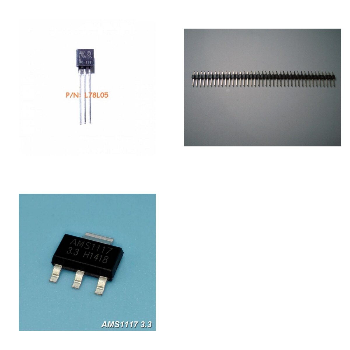
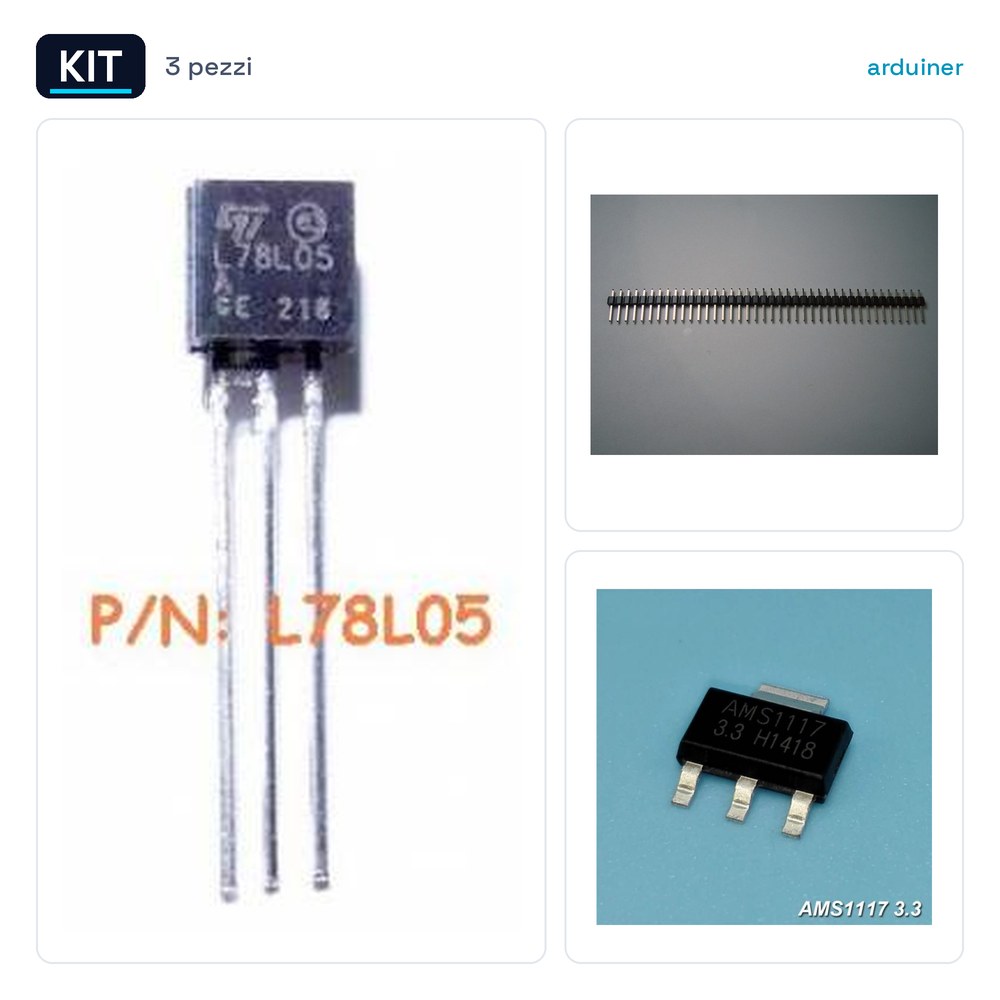
The ARD0014891 kit includes 15 pieces of IC L78L05, 4 pieces of Male Pin Header 2.54 1*40, and 5 pieces of IC AMS1117-3.3V. These components are useful for projects requiring voltage regulation and connectors for Arduino boards and similar. L78L05 and AMS1117-3.3V are voltage regulator ICs used to reduce power supply voltage to lower and stable levels, while Male Pin Header is useful for connecting different parts of a circuit or for connecting expansion boards to a mother board.
L78L05 is a positive fixed output voltage regulator, while AMS1117-3.3V provides a 3.3V voltage. Male Pin Header 2.54 1*40 is useful for connecting electronic components to expansion boards or to Arduino mother boards. This kit is suitable for projects requiring voltage regulators and connectors.
To use this kit, a basic knowledge of electronics and how to connect components is required. Ensure to follow the voltage and current specifications of each component to avoid damage.
Key Specifications
| Parameter | Value |
| IC L78L05 Model | L78L05 |
| Quantity of IC L78L05 | 15 |
| Male Pin Header Model | 2.54 1*40 |
| Quantity of Male Pin Header | 4 |
| IC AMS1117-3.3V Model | AMS1117-3.3V |
| Quantity of IC AMS1117-3.3V | 5 |
| Output Voltage L78L05 | N/D (see manufacturer’s datasheet) |
| Output Voltage AMS1117-3.3V | 3.3V |
| Male Pin Header Dimensions | 2.54 1*40 |
| Container | N/D (see manufacturer’s datasheet) |
Installation and Usage
- Check the compatibility of the components with the project.
- Connect the Male Pin Header to an expansion board or an Arduino motherboard.
- Connect the IC L78L05 to the circuit following the manufacturer’s specifications.
- Connect the IC AMS1117-3.3V to the circuit following the manufacturer’s specifications.
- Test the circuit with a multimeter to verify proper function.
Compatibility and Requirements
- This kit is compatible with Arduino boards and similar.
- An adequate power supply is required to power the voltage regulators.
- A support circuit is needed to connect and manage the components.
Limitations and Important Notes
- Does not include external power supplies.
- Basic knowledge of electronics is required.
- Does not include circuit diagrams or detailed guides.
- Be aware of the voltage and current limits specified by the manufacturer.
Troubleshooting
The voltage regulator does not work.
Probable cause: Insufficient power supply voltage.
Solution: Check and adjust the power supply voltage.
Male pin header connections are not correct.
Probable cause: Damaged or misaligned pins.
Solution: Inspect and repair the pins.
Incorrect output voltage.
Probable cause: Incorrect connection or improper adjustment.
Solution: Check and correct the connections.
Voltage regulator is hot.
Probable cause: Overload or insufficient thermal dissipation.
Solution: Check thermal dissipation and reduce load if necessary.
Use cases
Parking sensor for the garage
Objective: Detect parking space occupancy.
What is needed: ARD0004891 kit.
Steps: 1) Connect the voltage regulator to a distance sensor. 2) Connect the distance sensor to an alarm system. 3) Test the alarm system.
Expected result: The alarm system signals parking occupancy.
Voltage regulator for a robotics project
Objective: Power the robot with stable voltage.
What’s needed: Kit ARD0014891.
Steps: 1) Connect the voltage regulator to the robot’s motor. 2) Connect the motor to the control system. 3) Test the control system.
Expected result: The robot operates with stable voltage.
Smart lighting system
Objective: Adjust lighting based on ambient light.
What’s needed: Kit ARD0014891.
Steps: 1) Connect the voltage regulator to a light sensor. 2) Connect the light sensor to a control system. 3) Test the control system.
Expected result: The lighting changes automatically based on ambient light.
Prototype project
Objective: Test electronic components.
What’s needed: Kit ARD0014891.
Steps: 1) Connect the components to the prototyping circuit. 2) Test the components. 3) Verify the correct function.
Expected result: The components work correctly.
Home security system
Objective: Detect movement and alert.
What is needed: Kit ARD0014891.
Steps: 1) Connect the voltage regulator to a motion detector. 2) Connect the motion detector to an alarm system. 3) Test the alarm system.
Expected result: The alarm system signals movement.
Industrial automation project
Objective: Adjust lighting based on presence.
What is needed: Kit ARD0014891.
Steps: 1) Connect the voltage regulator to a presence detector. 2) Connect the presence detector to a control system. 3) Test the control system.
Expected result: The lighting changes automatically based on presence.
Climate Monitoring System
Objective: Detect and record weather conditions.
What’s needed: Kit ARD0014891.
Steps: 1) Connect the voltage regulator to a temperature sensor. 2) Connect the temperature sensor to a recording system. 3) Test the recording system.
Expected result: Weather conditions are recorded correctly.
Temperature Sensor Prototyping Project
Objective: Test a temperature sensor.
What’s needed: Kit ARD0014891.
Steps: 1) Connect the voltage regulator to the temperature sensor. 2) Test the temperature sensor. 3) Verify correct functionality.
Expected result: The temperature sensor functions correctly.
In the package
- 15 pieces L78L05 IC Integrated Circuits, 4 pieces Pin Header Male 2.54 1*40, 5 pieces AMS1117-3.3V IC Integrated Circuits
Complete the project
- 4 Pieces Male Pin Header 2.54 1*40 Arduino: To connect electronic components to expansion boards.
- 6 Pieces Bent Header Pin Male 2.54 1*40: To add additional connectors to the circuit.
- 4 Pieces Blue 1*40 2.54 in gold plated copper, Male pin header
Technical FAQ
How to connect the voltage regulator?
Connect the input to the positive terminal of the power supply, the output to the positive terminal of the circuit, and the common negative terminal to both.
Why is the voltage regulator hot?
Overload or insufficient thermal dissipation. Check the thermal dissipation and reduce the load if necessary.
Which pin headers are included in the kit?
4 pieces of Male Pin Header 2.54 1*40.
How to test the circuit?
Use a multimeter to verify the proper functioning of the circuit.
Reviews
There are no reviews yet.