 EN
 IT Italiano
 ES Español
 FR Français
 DE Deutsch
Description
What it is
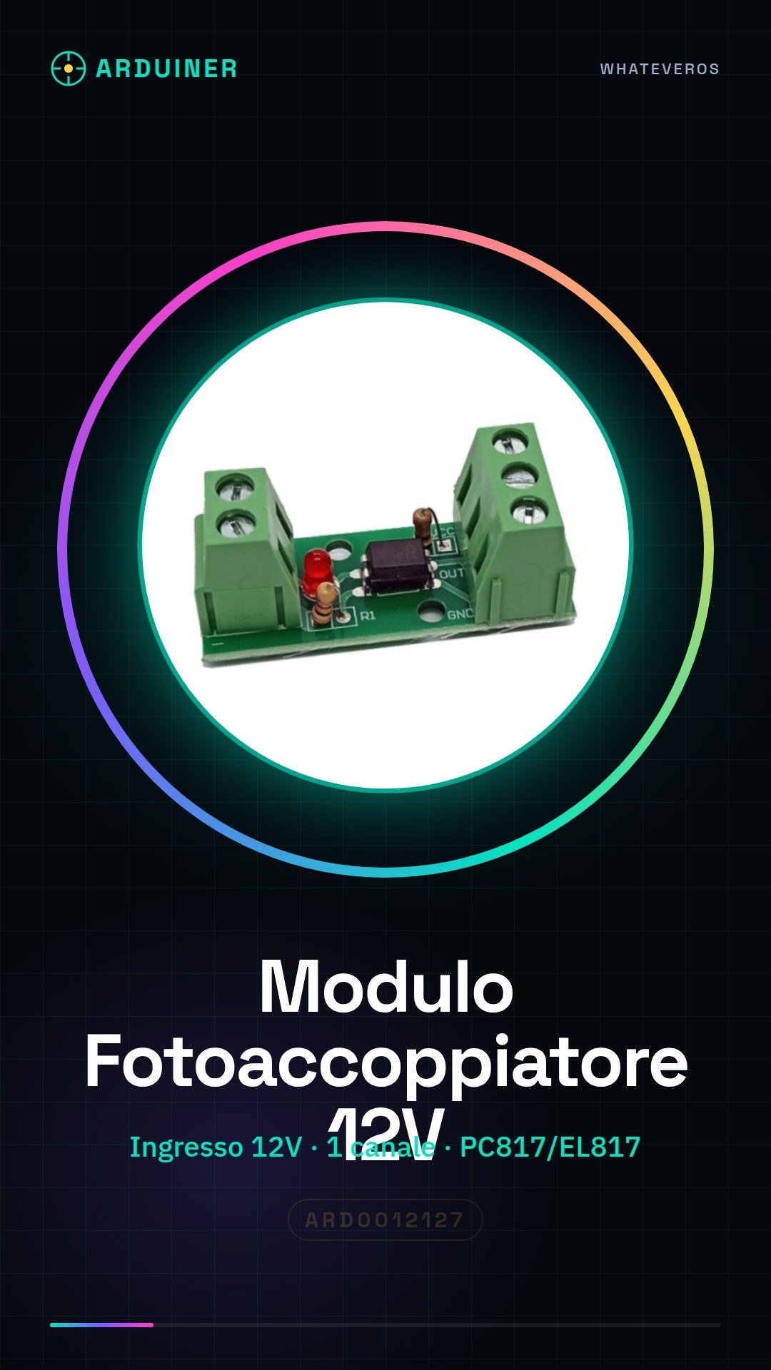
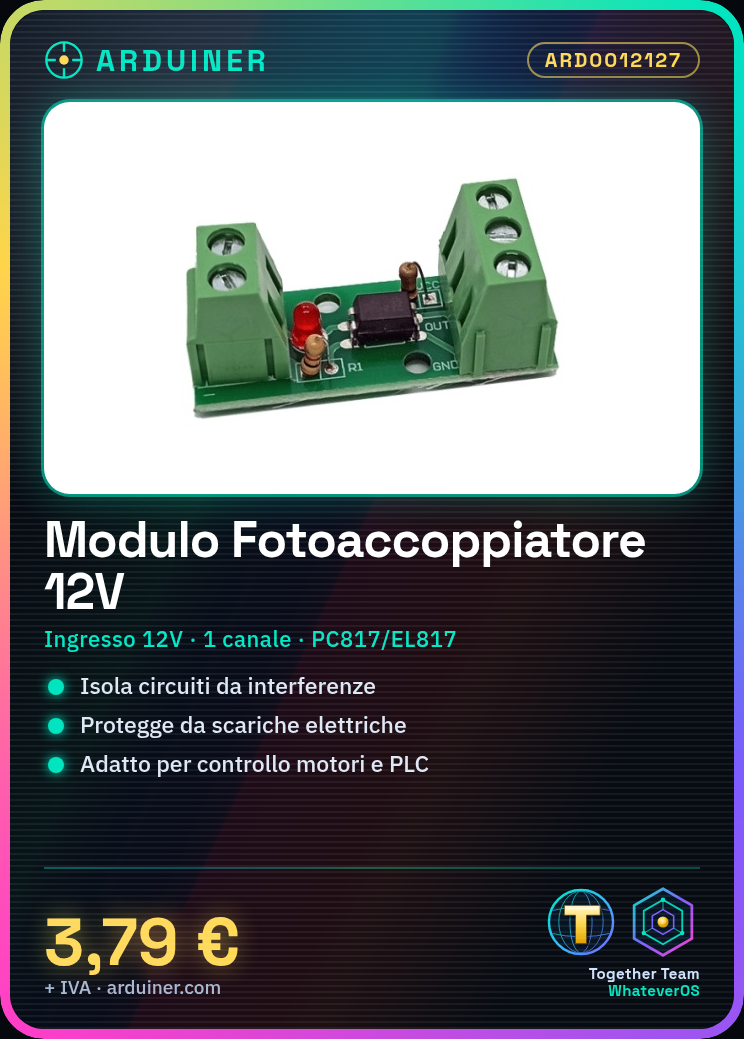
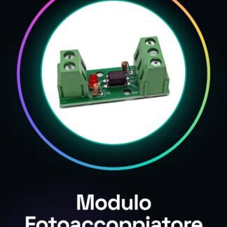
Photo Coupler Isolation Module with 1 channel, input 12V, based on the PC817/EL817 component. It allows for isolating electronic circuits, protecting them from interference and electrical discharges.
Features
- Input Voltage: 12V
- Isolation Type: Photo Coupler
- Channels: 1
- Components: PC817/EL817
What it is for
Ideal for protecting sensitive circuits from electronic interference, especially in motor control and PLC applications. It can be used with Arduino and other microcontrollers to isolate control signals and protect the main circuit.
Tutorial: How to Use Photo Coupler Isolation Module PC817
This photo coupler isolation module PC817 is ideal for protecting sensitive circuits from electronic interference. It is particularly useful for makers working on motor control and PLC projects.
What you need
- Arduino Uno
- Wing Pin Connections
- Breadboard Pin Connections
- 12V Power Supply
- Power Supply Cable
Steps
- Connect the 12V power supply to the module (check the datasheet for specific pins).
- Connect the control signal from Arduino to the input pin of the module (check the datasheet for specific pins).
- Connect the output signal from the module to the control device (e.g., a relay or motor driver).
- Ensure the module is properly powered and that the indicator LED is lit.
- Write an Arduino sketch that sends PWM or digital signals to the isolation module.
- Test the communication between Arduino and the isolation module.
- Configure the control device to receive signals from the isolation module.
- Verify the full system operation.
Example code
void setup() {
  pinMode(2, OUTPUT);
}

void loop() {
  digitalWrite(2, HIGH);
  delay(1000);
  digitalWrite(2, LOW);
  delay(1000);
}
Mini project
Create a DC motor control system using Arduino and the photo-isolator module. Connect the motor driver to the module and control the motor via Arduino.
Common mistakes
- Do not verify the correct power supply voltage on the datasheet.
- Connect the control signal to the wrong pin of the module.
- Do not configure the control device correctly to receive signals.
- Do not check the module’s LED indicator.
Recommended accessories
- Motors driver
- Relay
- Position sensors
- 12V power supply
Frequently asked questions
What is the minimum power supply voltage for this module?
Check the datasheet for the minimum power supply voltage.
Can I use this module with 5V?
No, the module is designed for 12V. Check the datasheet for voltage specifications.
What is the maximum connection distance between Arduino and the module?
The maximum distance depends on the quality of the cable and environmental conditions. Check the datasheet for specific guidelines.
Reviews
There are no reviews yet.