 EN
 IT Italiano
 ES Español
 FR Français
 DE Deutsch
Description
Technical Description
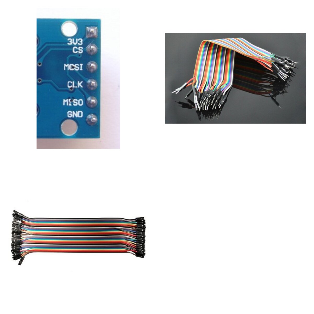
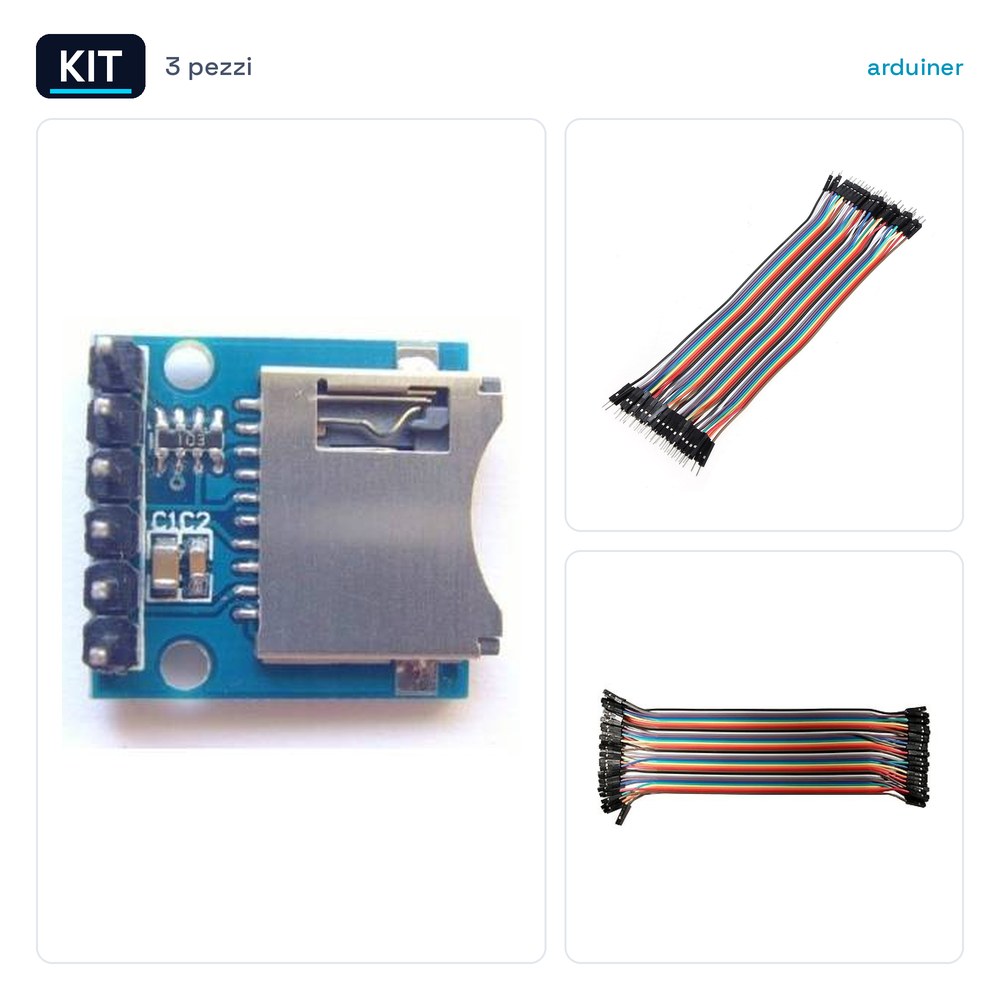
The Mini SD Card Module Kit + 40 Jumper Cables 20cm Male-Male + 40 Jumper Cables 20cm Female-Female is a set of components useful for projects that require data storage and access on SD cards. The SD module allows reading and writing data on standard SD cards, while the jumper cables provide connectors for building circuits on a breadboard or connecting various electronic modules.
The SD module is designed to be easily integrated into Arduino and similar projects, providing a simple and direct interface for accessing data on SD cards. The jumper cables, available in both male-male and female-female versions, are suitable for flexibly and securely connecting various electronic components.
This kit is particularly useful for projects that require data storage, log archiving, or the management of large amounts of information. The availability of a wide assortment of jumper cables allows for robust and reliable connections between the various components of the project.
Key Specifications
| Parameter | Value |
| Model | Mini SD Card Module Micro SD Card Module |
| Quantity | 1 |
| Supply Voltage | N/D (see manufacturer’s datasheet) |
| Dimensions | N/D (see manufacturer’s datasheet) |
| Interface | SD Card |
| Holder | N/D (see manufacturer’s datasheet) |
| Model | Jumper Cables 20cm Male-Male |
| Quantity | 40 |
| Power Supply Voltage | N/D (see manufacturer’s datasheet) |
| Dimensions | N/D (see manufacturer’s datasheet) |
| Interface | Pin |
| Container | N/D (see manufacturer’s datasheet) |
| Model | 20cm Female-Female Jumper Wires |
| Quantity | 40 |
| Power Supply Voltage | N/D (see manufacturer’s datasheet) |
| Dimensions | N/D (see manufacturer’s datasheet) |
| Interface | Pin |
| Container | N/D (see the manufacturer’s technical sheet) |
Installation and Usage
- Connect the SD module to the breadboard or circuit using male-male and female-female jumper cables.
- Ensure that the connectors are securely inserted into the breadboard holes or module connectors.
- Connect the SD module to the microcontroller or main circuit using jumper cables.
- Check the proper power supply of the SD module and the circuit.
- Run a simple test sketch to verify the correct communication between the SD module and the microcontroller.
Compatibility and Requirements
- The SD module is compatible with microcontrollers such as Arduino, Raspberry Pi, and similar systems.
- Jumper cables can be used with various electronic components and breadboards.
- To use the SD module, a compatible microcontroller or data processing system is required.
Limitations and Important Notes
- The SD module does not support reading and writing data on large SD cards without further configurations.
- Jumper wires can suffer damage if used in environments with high humidity or dust.
- Ensure that the connectors are properly inserted to avoid short circuits or communication interruptions.
Troubleshooting
The SD module is not recognized by the microcontroller.
Probable cause: The SD module connectors are not properly inserted into the breadboard or circuit.
Solution: Remove and reinsert the SD module connectors, ensuring they are properly inserted.
Data is not being saved correctly to the SD card.
Probable cause: The SD module is not properly powered or the microcontroller is not sending data correctly.
Solution: Verify the proper power supply to the SD module and check the microcontroller code to ensure data is being sent correctly.
The jumper wires can be easily disconnected.
Probable cause: The jumper wire connectors are damaged or the breadboard is dirty.
Solution: Remove and clean the jumper wire connectors and the breadboard before reinserting the connectors.
The SD module does not respond during data reading.
Probable cause: The SD card is damaged or has not been formatted correctly.
Solution: Remove and reinsert the SD card and verify that it has been formatted correctly.
Use cases
Parking sensor for the garage
Objective: To detect parking space occupancy in a garage.
What is needed: SD module to store detection data.
Steps: 1) Install the SD card module in the circuit. 2) Connect the distance sensor to the SD card module. 3) Write a code to store the detection data. 4) Verify the correct storage of the data.
Expected result: The system detects parking space occupancy and stores the data on an SD card.
Weather Monitoring System
Objective: Monitor weather conditions in a specific area.
What is needed: SD card module to store monitoring data.
Steps: 1) Install the SD card module in the circuit. 2) Connect the temperature and humidity sensors to the SD card module. 3) Write a code to store the monitoring data. 4) Verify the correct storage of the data.
Expected result: The system stores weather monitoring data on an SD card.
Audio Recording System
Objective: Record conversations or events on audio support.
What is needed: SD module to store audio data.
Steps: 1) Install the SD module in the circuit. 2) Connect the microphone to the SD module. 3) Write a code to store audio data. 4) Verify the correct storage of data.
Expected result: The system records audio data on an SD card.
Energy Monitoring System
Objective: Monitor energy usage in a home.
What is needed: SD module to store monitoring data.
Steps: 1) Install the SD module in the circuit. 2) Connect the electricity consumption sensors to the SD module. 3) Write a code to store monitoring data. 4) Verify the correct storage of data.
Expected result: The system stores energy monitoring data on an SD card.
Security Monitoring System
Objective: Monitor security conditions in a specific area.
What is needed: SD module to store monitoring data.
Steps: 1) Install the SD module in the circuit. 2) Connect the motion and door opening sensors to the SD module. 3) Write a code to store monitoring data. 4) Verify the correct storage of data.
Expected result: The system stores security monitoring data on an SD card.
Air quality monitoring system
Objective: Monitor air quality in a specific area.
What is needed: SD module to store monitoring data.
Steps: 1) Install the SD module in the circuit. 2) Connect the air quality sensors to the SD module. 3) Write a code to store monitoring data. 4) Verify the correct storage of data.
Expected result: The system stores air quality monitoring data on an SD card.
Traffic Monitoring System
Objective: Monitor traffic in a specific area.
What’s needed: SD card module to store monitoring data.
Steps: 1) Install the SD card module in the circuit. 2) Connect traffic sensors to the SD card module. 3) Write code to store monitoring data. 4) Verify correct data storage.
Expected result: The system stores traffic monitoring data on an SD card.
Temperature Monitoring System
Objective: Monitor temperature in a specific area.
What’s needed: SD card module to store monitoring data.
Steps: 1) Install the SD card module in the circuit. 2) Connect temperature sensors to the SD card module. 3) Write code to store monitoring data. 4) Verify correct data storage.
Expected result: The system stores the temperature monitoring data on an SD card.
In the package
- 1 Kit Mini SD Card Module + 40 Jumper Wires 20cm Male-Male + 40 Jumper Wires 20cm Female-Female
Complete the project
- 40 Jumper Wires 20cm Male-Female for Arduino: To connect the SD module to various electronic components.
Technical FAQs
The SD module is not recognized by the microcontroller?
Check that the SD module connectors are properly inserted into the breadboard or circuit.
The data is not being saved correctly on the SD card?
Check the proper power supply to the SD module and verify the microcontroller code to ensure that the data is being sent correctly.
Do the jumper wires come loose easily?
Check that the jumper wire connectors are properly inserted and clean.
The SD module does not respond during data reading?
Check that the SD card is properly formatted and not damaged.
Reviews
There are no reviews yet.