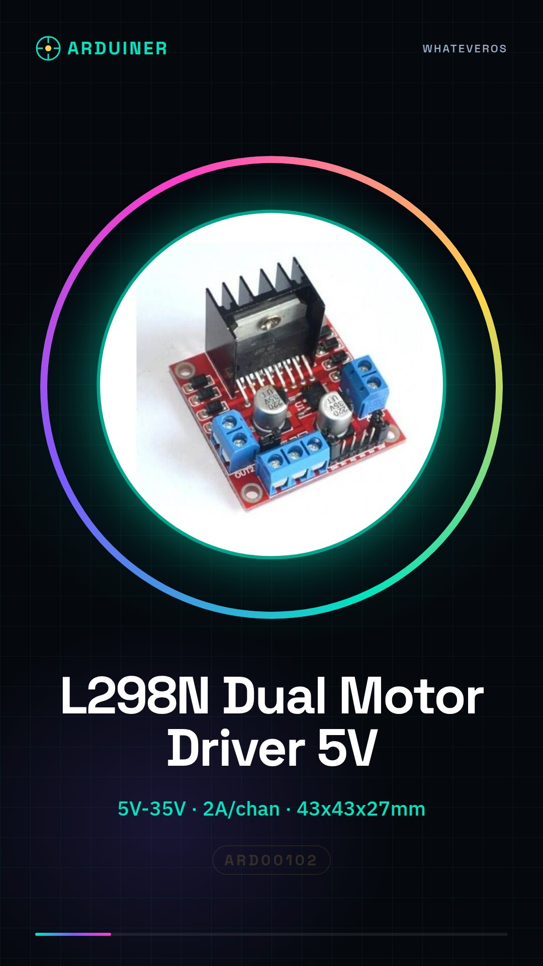
Description
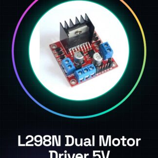
{‘Complete Description’: ‘L298N Dual H-Bridge Stepper Motor Driver – Control Module 5V for Robot Smart Car Key Features The L298N Dual H-Bridge Stepper Motor Driver is an electronic component designed to control two DC motors or a bipolar stepper motor using digital signals from a microcontroller board like Arduino. Feature Value Supply Voltage 5V – 35V Maximum Current 2A per channel Control Chip L298N Output Channels 2 (A and B) Logic Control 5V TTL Thermal Protection Yes Typical Dimensions Approximately 43 x 43 x 27 mm Functionality Independent control of two DC motors or a stepper motor. Supports PWM function to vary motor speed. Includes an integrated 5V voltage regulator (enable/disable via jumper). Features screw terminals for quick connections of the motors and power supply. Equipped with a heat sink to improve thermal dissipation. Module Pinout Pin/Terminal Description IN1, IN2 Motor A Control IN3, IN4 Motor B Control ENA PWM for Motor A ENB PWM for Motor B OUT1, OUT2 Motor A Connection OUT3, OUT4 Motor B Connection VCC Motors Power Supply (up to 35V) GND Common Ground 5V Logic Output or Input (depending on the jumper 5V enable) Basic Wiring Diagram for a DC Motor OUT1 and OUT2 → DC motor IN1 (pin 8 Arduino) → control direction 1 IN2 (pin 9 Arduino) → control direction 2 ENA (pin 10 Arduino) → PWM (speed) VCC → power supply 12V (e.g., from battery) GND → GND Arduino 5V → if necessary, enable jumper 5V to power logic Example Arduino Code: Control of a DC Motor // Defined pins int in1 = 8; int in2 = 9; int enA = 10; void setup() { pinMode(in1, OUTPUT); pinMode(in2, OUTPUT); pinMode(enA, OUTPUT); } void loop() { // Rotate one direction digitalWrite(in1, HIGH); digitalWrite(in2, LOW); analogWrite(enA, 150); // Speed: 0-255 delay(2000); // Stop the motor analogWrite(enA, 0); delay(1000); // Rotate in the other direction digitalWrite(in1, LOW); digitalWrite(in2, HIGH); analogWrite(enA, 200); delay(2000); // Stop the motor analogWrite(enA, 0); delay(1000); } Control of a Bipolar Stepper Motor Connect the stepper motor as follows: Wire 1 and 2 → OUT1 and OUT2 Wire 3 and 4 → OUT3 and OUT4 Use IN1, IN2, IN3, IN4 for control. Example Arduino Code: Stepper Motor (without library) int IN1 = 8; int IN2 = 9; int IN3 = 10; int IN4 = 11; void setup() { pinMode(IN1, OUTPUT); pinMode(IN2, OUTPUT); pinMode(IN3, OUTPUT); pinMode(IN4, OUTPUT); }’}
Reviews
There are no reviews yet.